Page 500 - Instrumentation Reference Book 3E
P. 500

Digital frequency and period/time-interval measurement 483

                                                       counters  often  employ both methods,  using  the
              Narrow                       Wide hysteresis
                                                       conventional  method  to  obtain  the  high  reso-
                                                       lution at high frequencies.
                                                         The period,  TI, of the input wave is calculated
                                                       from
                                                               1
                 --JFxArL                                  T.--=          Gating period
                                                              f;  Number of  cycles of  input waveform
                                                            1-
                   \  \ /                                      Iz,,c  x  10-7
                                                             -
                 False countscaused by                       -
                 noise                                            I11
                              (a)                      with a relative resolution of kl in nose.
                                                         The accuracy of frequency counters is limited
                            Measured
                                                       by four factors. These are the system resolution,
                                                       and  trigger,  systematic,  and  time-base  errors.
                   Hysteresis t                        Trigger error (TE) is the  absolute measurement
                   band                                error due to input noise causing triggering which
                                                       is too early  or too late.  For  a  sinusoidal  input
                                                       waveform it is given by
                            Pulse
                            duration                              1
                              (b)                          TE = -f-   (input signal to noise ratio)
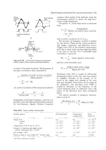
              Figure 20.76  (a) The use of  hysteresis to reduce the   76
              effects of noise; (b) timing errors caused by hysteresis.   and for a non-sinusoidal wave
                                                                 Peak-to-peak noise voltage
              of cycles of the input waveform. The frequency of   TE=&   Signal slew rate
              the input waveform is thus calculated as
                                                       Systematic  error  (SE)  is  caused  by  differential
                     Number  of  cycles of  input waveform   propagation  delays in the start and stop sensors
                  A=          Gating period            or  amplifier  channels  of  the  counter;  or  by

                      Ili                              errors  in  the  trigger  level  settings  of  the  start
                   = - 10-7  H~                        and stop channels. These errors can be removed
                         x
                     %SC
                                                       by  calibration.  The  time-base  error  (TBE)  is
                                                       caused  by  deviation  on  the  frequency  of  the
              The relative resolution of the reciprocal method is   crystal frequency from its calibrated  value. The
                             -  lo-’
                      10-7   -*-=*-      1             causes  of  the  deviation  have  been  considered
                                                       above.
                   Gating time    f,    nose             The  relative  accuracy  of  frequency  measure-
                                                       ment is given by
              independent of the input frequency, and thus it is   Resolution of J;  TE
              possible to provide high-resolution measurements   f         - i Relative TBE
              for  lowfrequency  signals.  Modern  frequency      .A        ts

              Table 20.10  Quartz oscillator characteristics
              Stnbilitji against                      Uncoipipensated   Twiperatuw   Oven
                                                                      coinpensated   stabilized
              Aging: E4 h                             n.a.            n.a.
                    lmonth                            <5  x  10-7      <I x  10-7
                    /year                             <5  x  10-6      <I x  10-7
              Temperature: 0-50°C  ref. to f23”C      <I  x  so-5      <1 x  10-6
              Change in measuring and supply mode:    <3  x  10-7      <5 x  10-8
                linehnt. battery/ext. D.C. 12-26V
              Line voltage: &IO%                      <1 x  10-3       <i   so-9     <j x
              Warm-up time to reach within  lo-’  of final value   n.a.   n.a        <15min
                ~~
              -‘:After 4S h of continuous operation.
   495   496   497   498   499   500   501   502   503   504   505