
Page 496 - Instrumentation Reference Book 3E
P. 496
Digital frequency and period/time-interval measurement 479
OIP Gu OIP oi B"
I I
zs R
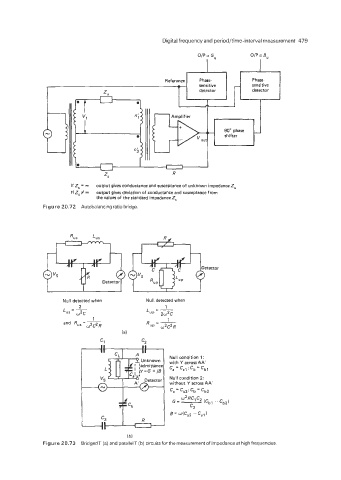
output gives conductance and susceptance of unknown impedance 2,
15 2, = 00
If Z, #-J output gives deviation of conductance and susceptance from
the values of the standard impedanceZ,
Figure 20.72 Autobalancing ratio bridge
etector
Null detected when Null detected when
1
L =- 2 Lu,= -
us 02c 2w2c
1
1
and R,, = __ R"P = w2C2R
W*C2R
la)
C1 c2
Null condition 2:
without Y across AA'
c, = Ca2; Cb = Cb2
(b)
Figure 20.73 BridgedT (a) and parallelT (b) circuits for the measurement of impedance at high frequencies.