
Page 492 - Instrumentation Reference Book 3E
P. 492
The measurement of resistance, capacitance, and inductance 475
switch
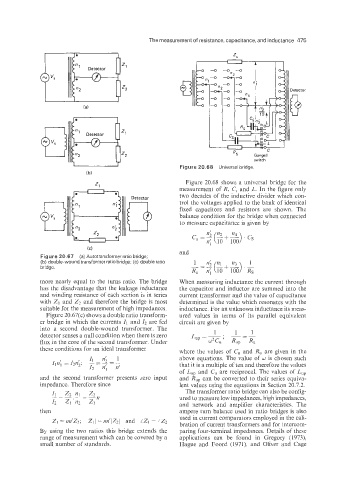
Figure 20.68 Universal bridge.
Figure 20.68 shows a universal bridge for the
measurement of R, C, and L. In the figure only
two decades of the inductive divider which con-
0
Detector
trol the voltages applied to the bank of identical
fixed capacitors and resistors are shown. The
balance condition for the bridge when connected
to measure capacitance is given by
and
Figure 20.67 (a) Autotransformer ratio bridge;
(b) double-wound transformer ratio bridge; (c) double ratio 1
bridge.
more nearly equal to the turns ratio. The bridge When measuring inductance the current through
has the disadvantage that the leakage inductance the capacitor and inductor are summed into the
and winding resistance of each section is in series current transformer and the value of capacitance
with Z1 and Z2 and therefore the bridge is most determined is the value which resonates with the
suitable for the measurement of high impedances. inductance. For an unknown inductance its meas-
Figure 20.67(c) shows a double ratio transform- ured values in terms of its parallel equivalent
er bridge in which the currents 11 and 12 are fed circuit are given by
into a second double-wound transformer. The
detector senses a null condition when there is zero
flux in the core of the second transformer. Under
these conditions for an ideal transformer where the values of C, and R, are given in the
above equations. The value of LU‘ is chosen such
that it is a multiple of ten and therefore the values
of L,, and C, are reciprocal. The values cf L,,
and the second transformer presents zero input and R,, can be converted to their series equiva-
impedance. Therefore since lent values using the equations in Section 20.7.2.
The transformer ratio bridge can also be config-
ured to measure low impedances, high impedances,
and network and amplifier characteristics. The
then ampere turn balance used in ratio bridges is also
Z1 = nn’Z2; /Z1/ = nn’1Zzl and iZ1 = LZ2 used in current comparators employed in the cali-
bration of current transformers and for intercom-
By using the two ratios this bridge extends the paring four-terminal impedances. Details of these
range of measurement which can be covered by a applications can be found in Gregory (1973):
small number of standards. Hague and Foord (1971), and Oliver and Cage