Page 490 - Instrumentation Reference Book 3E
P. 490

The measurement of resistance, capacitance, and inductance 473

                                                                          For an ideal transformer
                                                                    n1 turns


                                                                    n2 turns


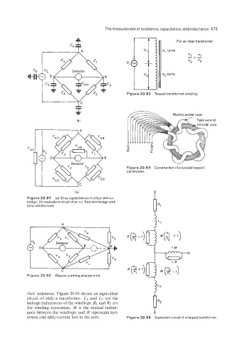
                                                      Figure 20.63  Tapped transformer winding.


                                                                                        und
                                                                                        core


                                                                         W
                                                      Figure 20.64 Construction ofatoroidal tapped
                                                     transformer.


                                Ib)
             Figure 20.61  (a) Straycapacltances in afour-arm a.c.
            bridge; (b) equivalent circuit of an a.c. four-arm bridge with
            stray admittances.


                           A


                           C
             Figure 20.62  Wagnerearthing arrangement


             their resistance. Figure 20.65 shows an equivalent
             circuit  of  such a  tramformer.  L1  and L2  are the
             leakage inductances of the windings; R1 and R2 are
             the winding resistances; M  is the mutual  induct-
             ance between the windings; and R represents hys-
             teresis and eddy-current loss in the core.   Figure 20.65  Equivalent circuit of a tapped transformer.
   485   486   487   488   489   490   491   492   493   494   495