
Page 494 - Instrumentation Reference Book 3E
P. 494
The measurement of resistance, capacitance, and inductance 477
,ut
Detector ,
”; f
22
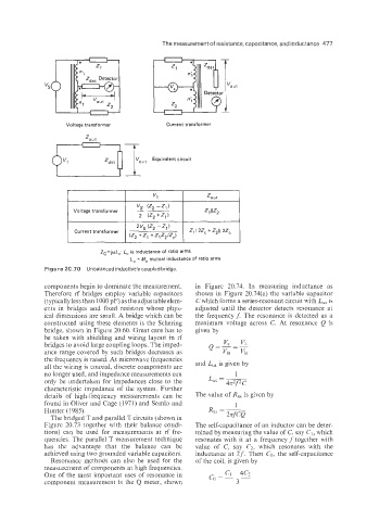
Voltage transformei Current transformer
Z0”t
7; Equivalent circuit
Ut
____
vs (Z2 -Z1)
Voltage transformer z1 llZZ
2 (Z, +Z,)
Current transformer -
(Z, +zl +Z,Zz/Zc)
Zc=jwL,: L, is inductance of ratio arms
L, = M, mutual inductance of ratio arms
Figure 20.70 Unbalanced inductivelycoupled bridge
components begin to dominate the measurement. in Figure 20.74. In measuring inductance as
Therefore rf bridges employ variable capacitors shown in Figure 20.74(a) the variable capacitor
(typically less than 1000 pF) as the adjustable elem- C which forms a series-resonant circuit with L,, is
ents in bridges and fixed resistors whose phys- adjusted until the detector detects resonance at
ical dimensions are small. A bridge which can be the frequency f. The resonance is detected as a
constructed using these elements is the Schering maximum voltage across C. At resonance Q is
bridge, shown in Figure 20.60. Great care has to given by
be taken with shielding and wiring layout in rf
bridges to avoid large coupling loops. The imped-
ance range covered by such bridges decreases as
the frequency is raised. At microwave frequencies
all the wiring is coaxial, discrete components are and L,, is given by
no longer used, and impedance measurements can 1
only be undertaken for impedances close to the LIE =
characteristic impedance of the system. Further
details of high-frequency measurements can be The value of R,, is given by
found in Oliver and Cage (1971) and Somlo and 1
Hunter (1985). R,s = &
The bridged T and parallel T circuits (shown in
F:gure 70.73 together with their balance condi- The self-capacitance of an inductor can be deter-
tions) can be used for measurements at rf fre- mined by measuring the value of C; say C1, which
quencies. The parallel T measurement technique resonates with it at a frequency f together with
has the advantage that the balance can be value of C, say C,, which resonates with the
achieved using two grounded variable capacitors. inductance at 2 f. Then Co, the self-capacitance
Resonance methods can also be used for the of the coil, is given by
measurement of components at high frequencies.
One of the most important uses of resonance in
component measurement is the Q meter, shown