
Page 498 - Instrumentation Reference Book 3E
P. 498
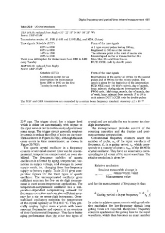
Digital frequency and period/time-interval measurement  481

              Table 20.9  UK time broadcasts
              GBR 16kHz rcidiated.from Rugby (52  22'  13"  N  01 ' 10' 25"  W)
              Power: ERP 65 kW
              Transmission modes: AI, FSK (16.00 and 15.95kHzf. and MSK (future)
              Time signals: Schedule (UTC)               Form of the time signals
                          5255 to 0300                   A  1 type second pulses lasting 100 ms,
                          0855 to 0900                   lengthened to 500ms at the minute
                          1455 to  1500                  The reference point is the start of carrier rise
                          2055 to 2100                   Unintermpted carrier is transmitted for 24 s
              There is an interruption for maintenance from 1000 to 1400   from 54 m 30 s and from 0 m 6 s
              every Tuesday                              DUT 1 :CCIR code by double pulses
              MSF 60 kHz rndiotedfiarn Rugby
              Power: ERP 27 kW
                          Schedule (UTC)                 Form of the time signals
                          Continuous except for an       Interruptions of the carrier of 100 ms for the second
                          interruption for maintenance   pulses and of 500ms for the minute pulses. The
                          from 1000 to 1400 on the first   epoch is given by the beginning of the interruption
                          Tuesday in each month          BCD NRZ code, 100 bitds (month, day of month,
                                                         hour, minute), during minute interruptions BCD
                                                         PWM code, lbit/s (year, month. day of month, day
                                                         of week, hour, minute) from seconds 17 to 59 in
                                                         each minute DUT1:CCIR code by double pulses
              The MSF and GBR transmission are controlled by a cesium beam frequency standard. Accuracy t2 x


              20V rms.  The trigger circuit has  a  trigger level   crystal and are suitable for use in seven- to nine-
              which  is either set  automatically with respect  to   digit instruments.
              the input wave or can be continuously adjusted over   The  microprocessor provides  control  of  the
              some range. The triser circuit generally employs   counting operation  and  the  display  and  post-
              hysteresis to reduce the effect of noise on the wave   measurement computation.
              form as shown  in Figure 20.76(a), although this can   Conventional  frequency  counters  count  the
              cause errors in  time measurement, as  shown  in   number of  cycles,  ni, of  the  input  waveform  of
              Figure 20.76(b).                         frequency,  A, in a gating period, tg, which corre-
                The  quartz  crystal  oscillator  in  a  frequency   sponds to a number of counts, no=, of the 10-MHz
              counter or universal counter timer can be uncom-   crystal oscillator. They have an uncertainty corre-
              pensated, temperature compensated, or oven sta-   sponding to fl count of the inpat waveform. The
              bilized.  The  frequency  stability  of  quartz   relative resolution is given by
              oscillators is affected by aging, temperature, var-
              iations in supply voltage, and changes in power   Relative resolution
              supply mode, Le.,  changing from line-frequency
              supply to battery supply. Table '0.10  gives com-   Smallest measurable change in
              parative  figures  for  the  three  types  of  quartz    measurement value
              oscillator.  The  uncompensated  oscillator  gives   Measurement value
              sufficient accuracy for five- or six-digit measure-
              ment in most room-temperature applications. The   and for the measurement of frequency is thus
              temperaturscompensated oscillator  has  a  tem-
              perature-dependent  compensating  network  for             1                 1
                                                                                      - f-
              frequency correction and can give suficient accu-   * Gating period x  input frequency  -
              racy for a  six- or seven-digit instrument. Oven-                           t,
              stabilized  oscillators maintain  the  temperature
              of the crystal typically at 70 f 0.01 "C. They gen-   In order to achieve measurements with good rela-
              erally  employ  higher  mass  crystals with  lower   tive  resolution  for  low-frequency  signals  long
              resonant frequencies and operate at an overtone   gating times are required. Reciprocal frequency
              of their fundamental frequency. They have better   counters synchronize the gating time to the input
              aging performance than  the  other two types of   waveform, which then becomes an exact number