
Page 502 - Instrumentation Reference Book 3E
P. 502
Digital frequency and period/time-interval measurement 485
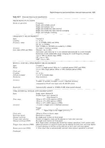
Table 20.11 Universal timer/counter specifications
MEASURING FUNCTIONS
Modes of uperrition Frequency
Single and multiple period
Single and multiple ratio
Single and double-line time interval
Single and double-line time interval averaging
Single and multiple totalizing
FREQUENCY MEASUREMENT
Inpzrt Channel A
Coupling ax. or d.c.
Fiepenry range d.c. to 50 MHz (9902 and 9904)
HF d.c. to 30MHz
VHF 10 MHz to 200 MHz pre-scaled by 4 (9906)
Accuracy fl count f timebase accuracy
Gate times (9000 and 9902) Manual: 1 ms to 100 s
Automatic: gate times up to 1 s are selected automatically to avoid overspill
Hysteresis avoids undesirable range changing for small frequency changes
1 ms to 100 s in decade steps (9904)
HF: lms to 100s
VHF: 4 ms to 400 s
SINGLE- AND MULTIPLE-PERIOD MEASUREMENT
Ii?put Channel A
Range 1 ps to 1 s single period 100 ns to 1 s multiple period (9902 and 9904)
1 ps to 100s single period lOOns to 100s multiple period (9906)
Clock irnir 1 PS
Coupling a.c. or d.c.
Periods ai'evaged 1 to 10' in decade steps
Resolirtion 10 ps maximum
Accirrocy &0.3%
Number of periods averaged ?C count f timebase accuracy
(measured at 50 mV rnis input with 40 dB SIN ratio)
Bandwidth Automatically reduced to 10 MHz (3 dB) when period selected
TIME INTERVAL SINGLE AND DOUBLE INPUT
Input Single input: channel B
Double input: start channel B
stop channel A
Time range lO0ns to 1O4s (2.8h approx.) (9902)
100 ns to lo5 s (28 h approx.) (9904)
100 ns to 106 s (280 h approx.) (9906)
&1 coun? f trigger error k timebase accuracy
Trigger
error = 5
ns
Signal slope at the trigger point (v~wi~)
Clock irnits lOOns to lOms in decade steps
Startlstop signals Electrical or contact
Mamru1 siartlstop By single push button on front panel
Trigger slope selection Positive or negative slope can be selected on both start and stop
A4unziul siartlstop (9900) By single push button on front panel
N.B. Input socket automatically biased for contact operation (1 mA current sink)
Tvigger slope selection (9900) Electrical-positive or negative slopes can be selected on both start and stop signals
Contact-opening or closure can be selected on both start and stop signals
Boirnce protection (9900) A lOms dead time is automatically included when contact operation is selected
Continued