
Page 503 - Instrumentation Reference Book 3E
P. 503
486 Electrical measurements
Table 20.11 Continued
TIME-INTERVAL AVERAGING SINGLE AND DOUBLE INPUT
znpllt Single input: channel B
Double input: Start channel B
Stop channel A
Time range 15011s to 100ms (9902)
15011s to 1 s 9904
150ns to 10s (9906)
Dead time betieeen intervals 150ns
Clock unit IOOns
Time intervuls averaged 1 to IO’ in decade steps
Resolution IOOns to Ips
Acctiracj~ &Timebase accuracy f system error f averaging error
System error: lOns per input channel. This is the difference in delays between start
and stop signals and can be minimized by matching externally
Trigger error f 100
Averaging error = ns
J (Intervals averaged)
5
Trigger error = . ns
Signal slope at the trigger point(V/ps)
-
RATIO
Higher-frequency input Channel A
Higher-frequency range 10 Hz to 30 MHz (9900)
d.c. to 50 MHz (9902. 9904)
Lower-frequencJ1 input Channel B
Lower-frequency range reads d.c. to 10MHz
Frequency A
Frequency B x 11
Mirltiplier n 1 to IO’ in decade steps
fl count i trigger error on Channel B
Accuracy No. of gated periods
5
Trigger error = , ns
Signal slope at the trigger point (V/p)
TOTALIZING
Input Channel A (IO MHz max.)
Max. rate lo7 events per second
Pulse width 50 ns minimum at trigger points
Ae-scaling Events can be pre-scaled in decade multiples (12) from 1 to IO5
No. of input events f 1 count - 0
Reads
n
Manual startlstop By single push button on front panel
Electrical startlstop By electrical signal applied to Channel B
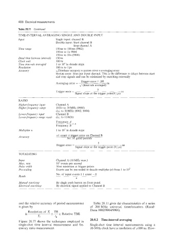
and the relative accuracy of period measurement Table 20.11 gives the characteristics of a series
is given by of 200-MHz universal timer/counters (Racal-
-
* Resolution of T, TE Dana 9902/9904/9906).
k - j, Relative TBE
Ti t,
20.8.2 Time-interval averaging
Figure 20.77 shows the techniques employed in
single-shot time interval measurement and fre- Single-shot time interval measurenients using a
quency ratio measurement. IO-MHz clock have a resolution of &IO0 ns. How-