
Page 491 - Instrumentation Reference Book 3E
P. 491
474 Electrical measurements
The ratio error from the ideal value of q/n2 is output across a single tap of the immediately
given approximately by higher decade. For the windings on a single core
the number of decades which can be accommo-
dated is limited by the need to maintain the volts/
turn constant over all the decades, and therefore
and this error can be made to be less than 1 part the number of turns per tap at the higher decade
in lo6. becomes large. Generally a compromise is made
The effect of loading is also small. An imped- between the number of cores and the number of
ance Z applied across the 122 winding gives a ratio decades on a single core.
error of
20.7.4. I Bridge configurations
(rzl/izd(R? + jwLd + (idnl)(R1 + jwh) x 100%
[(nl + n$22] . 2 There are three basic bridge configurations, as
shown in Figure 20.67. In Figure 20.67(a) the
For an equal bridge, with lil = n2, this is
detector indicates a null when
z1 - Vl
--
-
z2 v2
which is approximately the same error as if the
transformer consisted of a voltage source with an and for practical purposes
output impedance given by its leakage inductance
and the winding resistance. These can be made to
be small and thus the effective output impedance
of the transformer is low; therefore the loading Thus
effect is small. The input impedance of the wind-
ing seen by the a.c. source is determined by the Z1 = nZ2; [Zlj = nlZz[ and iZ1 = LZ,
mutual inductance of the windings (which is high)
and the loss resistance (which is also high). The bridge can therefore be used for comparing
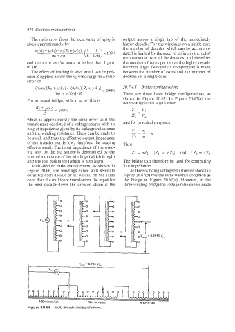
Multi-decade ratio transformers, as shown in like impedances.
Figure 10.66, use windings either with separate The three-winding voltage transformer shown in
cores for each decade or all wound on the same Figure 20.67(b) has the same balance condition as
core. For the multicore transformer the input for the bridge in Figure 20.67(a). However, in the
the next decade down the division chain is the three-winding bridge the voltage ratio can be made
t
I
lDon turnsltap 1On turnsltap n turnsltap
Figure 20.66 Multi-decade ratio transformers