
Page 481 - Instrumentation Reference Book 3E
P. 481
464 Electrical measurements
ture changes as R1 but no strain. The output from
the bridge is given by
J'S
vout = - { 1 - [l + (5/2)]
2
l
}
where
AR
6:-
R
For S< 1 the output of the bridge is linearly
related to the change in resistance, i.e.,
TI
V,
Figure 20.50 Wheatstone bridge v,,, = - S
'
4
Self-heating generally limits the bridge supply
between the points A and B of the bridge. A null voltage and hence the output voltage. Amplifica-
occurs when tion of the bridge output voltage has to be under-
taken with an amplifier having a high common-
mode rejection ratio (CMRR), since the output
from the bridge is in general small, and the corn-
The bridge is balanced either manually or mon-mode signal applied to the amplifier is V,/2.
automatically using the output signal from the Further details of amplifiers suitable for use as
detector in a feedback loop to find the null pos- bridge detectors can be found in Part 4.
ition. The null condition is independent of the The output from a strain gauge bridge can be
source resistance. R,, of the voltage source sup- increased if four gauges are employed, with two
plying the bridge or the sensitivity or input resist- being in tension and two in compression, as
ance, Rd, of the detector. These, however, shown in Figure 20.51(b). For such a bridge the
determine the precision with which balance con- output is given by
dition can be determined. The sensitivity, S, of Vo,, = k', ' 5
the bridge can be expressed as
Bridge output voltage, Vout,
for a change AR1 in RI
S=
Bridge supply voltage
Near the balance condition for a given fractional
change, 6, in R1 given by
AR
6 = L
RI
the sensitivity is given by
SRa
S=
4
CR,+Ra[2+(R7/R4)+(R1/R3)]
r=I
4
+ R,[2 + (R3/R1) + (RI lR3)] + RdRs (I/&)
r=l
With an electronic detector Rd can be made large,
and if R, is small then S is given by
which has a maximum value of S/4 when
(R3IRj) = 1.
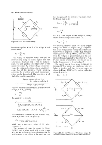
The unbalanced mode is shown in Figure
20.51(a) and is often used with strain gauges
(Chapter 4). Rl is the active strain gauge and R2 Figure 20.51 (a) Unbalanced Wheatstone bridge; (b)
is the dummy gauge subject to the same tempera- unbalanced Wheatstone bridge with increased sensitivity.