
Page 478 - Instrumentation Reference Book 3E
P. 478
Measurement of electrical energy 461
----
Waveguide RF shield
Accumulator -t---- 1 RF
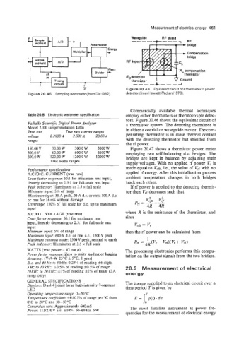
m Figure 20.46 Equivalent circuit of a thermistor rf power
Figure 20.45 Sampling wattmeter (from Dix1982). detector (from Hewlett-Packard 1978).
Commercially available thermal techniques
Table 20.8 Electronic wattmeter specification employ either thermistors or thermocouple detec-
tors. Figure 20.46 shows the equivalent circuit of
Valhalla Scientijk Digital Power Annlyzer a thermistor system. The detecting thermistor is
Model 2100 range/resolution table in either a coaxial or waveguide mount. The com-
True rins True rim cirrrent ranges
voltage 0.2000 A -1.000 A 20.00 A pensating thermistor is in close thermal contact
ranges with the detecting thermistor but shielded from
the rf power.
150.00 V 30.00 W 300.0 W 3000 W Figure 20.47 shows a thermistor power meter
300.0V 60.00 W 600.0 W 6000 W employing two self-balancing d.c. bridges. The
600.0 W 120.00 W 1700.0 W 12000 W bridges are kept in balance by adjusting their
True watts ranges supply voltages. With no applied rf power V, is
made equal to Vrm, Le., the value of Vrf with no
Perforniance specifications
A.C,/D.C. CURRENT (true rms) applied rf energy. After this initialization process
Crest ,facror response: 50: 1 for minimum rms input, ambient temperature changes in both bridges
linearly decreasing to 251 for full-scale rms input track each other.
Peak indicutor: Illuminates at 2.5 x full scale If rf power is applied to the detecting thermis-
Mininitini inpirr: 5'K of range tor then Vd decreases such that
Muxiniun7 input: 35 A peak, 20 A d.c. or rms: 100 A d.c.
or rms for 16mS without damage
Overrmige: 150% of full scale for d.c. up to maximum
input
A.C./D.C. VOLTAGE (true rms) where R is the resistance of the thermistor, and
Crest juctor response: 50 1 for minimum rms since
input, linearly decreasing to 251 for full-scale rms Vrm = Vc
input
Minimum input: 5%) of range then the rf power can be calculated from
Masiniziin input: 600V d.c. or rms a.c., l500V peak
Masimzm conm7on mode: 1500 V peak, neutral to earth 1
Peak indicator: Illuminates at 2.5 x full scale Prf = - (Vc - VrfM vc + VIf)
4R
WATTS (true power - VI cos Q) The processing electronics performs this compu-
Power jbctor response: Zero to unity leading or lagging tation on the output signals from the two bridges.
Accrwacv: (V-A-W 25°C f 5°C 1 vearl
D.c. mi; 40 H: 30 5 kHz: 0.25% of reading f6 digits
5 Hz io 10 kHz: It0.5'%1 of reading f0.5'%'nof range 20.5 Measurement of electrical
IOkHz to 2OkHz: fl'%l of reading fl'X of range (2A
range only) energy
Operating ten7jierature range: 0-50"C
Teniperaiure coejjicient: iO.O25'%1 of range per "C from E= 1: p(f).dt
0°C to 20°C and 30-50°C
Con1:ersioii rate: Approximately 600 mS The most familiar instrument at power fre-
Power: 115/23OV a.c. flO'K. 50-60%. 5W
quencies for the measurement of electrical energy