
Page 473 - Instrumentation Reference Book 3E
P. 473
456 Electrical measurements
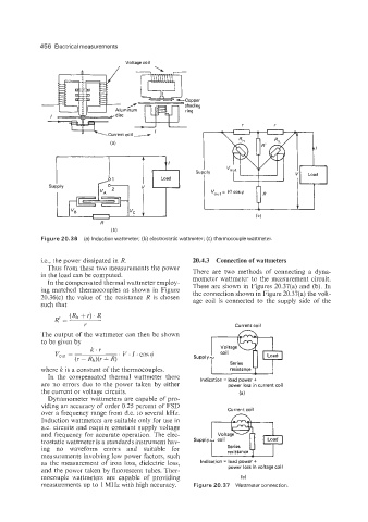
Figure 20.36 (a) Induction wattmeter; (b) electrostatic wattmeter; (c) thermocouple wattmeter.
Le., the power dissipated in R. 20.4.3 Connection of wattmeters
Thus from these two measurements the power
in the load can be computed. There are two methods of connecting a dyna-
mometer wattmeter to the measurement circuit.
In the compensated thermal wattmeter employ-
ing matched thermocouples as shown in Figure These are shown in Figures 20.37(a) and (b). In
the connection shown in Figure 20.37(a) the volt-
20.36(c) the value of the resistance R is chosen age coil is connected to the supply side of the
such that
Current coil
The output of the wattmeter can then be shown
to be given by
Voltage
coil
u
Series
where k is a constant of the thermocouples. resistance
In the compensated thermal wattmeter there Indication = load power +
are no errors due to the power taken by either power loss in current coil
the current or voltage circuits. (a)
Dynamometer wattmeters are capable of pro-
viding an accuracy of order 0.25 percent of FSD
over a frequency range from d.c. to several kHz. Current coil
Induction wattmeters are suitable only for use in
a.c. circuits and require constant supply voltage
and frequency for accurate operation. The elec-
trostatic wattmeter is a standards instrument hav-
ing no waveform errors and suitable for Series
measurements involving low power factors, such resistance
as the measurement of iron loss, dielectric loss, Indication = load power +
and the power taken by fluorescent tubes. Ther- power loss in voltage coil
mocouple wattmeters are capable of providing (b)
measurements up to 1 MHz with high accuracy. Figure 20.37 Wattmeter connection.