
Page 472 - Instrumentation Reference Book 3E
P. 472
Power measurement 455
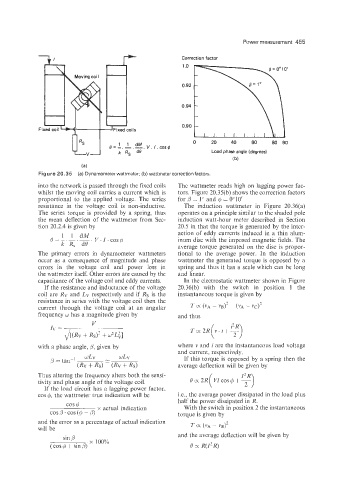
r+ Correction factor
1 .o
I L I
0.92
0.94
0.90
Fi oils L
0 20 40 60 80 90
Load phase angle (degrees)
(b)
Figure 20.35 (a) Dynamometer wattmeter; (b) wattmeter correctionfactors.
into the network is passed through the fixed coils The wattmeter reads high on lagging power fac-
whilst the moving coil carries a current which is tors. Figure 20.35(b) shows the correction factors
proportional to the applied voltage. The series for 0 = 1” and Q = 0010’
resistance in the voltage coil is non-inductive. The induction wattmeter in Figure 20.36(a)
The series torque is provided by a spring, thus operates on a principle similar to the shaded pole
the mean deflection of the wattmeter from Sec- induction watt-hour meter described in Section
tion 20.2.4 is given by 20.5 in that the torque is generated by the inter-
action of eddy currents induced in a thin alurn-
inum disc with the imposed magnetic fields. The
average torque generated on the disc is propor-
The primary errors in dynamometer wattmeters tional to the average power. In the induction
occur as a consequence of magnitude and phase wattmeter the generated torque is opposed by a
errors in the voltage coil and power loss in spring and thus it has a scale which can be long
%he watzmeter itself. Other errors are caused by the and linear.
capacitance of the voltage coil and eddy currents. In the electrostatic wattmeter shown in Figure
If the resistance and inductance of the voltage 20.36(b) with the switch in position 1 the
coil are R’v and LV respectively and if Rs is the instantaneous torque is given by
resistance in series with the voltage coil then the
current through the voltage coil at an angular T X ( VA - VB)~ (VA - 11~)~
~
frequency w has a magnitude given by and thus
v T cx 2R (v . i + T)
rv =
+
~[(Rv Rs)’ + W’LC]
with a phase angle, 0, given by where v and i are the instantaneous load voltage
and current, respectively.
If this torque is opposed by a spring then the
average deflection will be given by
Thus altering the frequency alters both the sensi-
tivity and phase angle of the voltage coil.
If the load circuit has a lagging power factor.
cos 0, the wattmeter true indication will be i.e., the average power dissipated in the load plus
cos 6 half the power dissipated in R.
With the switch in position 2 the instantaneous
x actual indication
cos ,3. cos (4 - 0) torque is given by
and the error as a percentage of actual indication TO( (vA - vBj2
will be
sin B and the average deflection will be given by
(cos Q + sin p, x 100% o cx R(Z?R)