
Page 474 - Instrumentation Reference Book 3E
P. 474
Power measurement 457
current coil. The wattmeter therefore measures transformers introduce errors in the measurement
the power loss in the load plus the power loss in as outlined in Section 30.2.3.
the current coil. With the wattmeter connected as
in Figure 20.37(b) the current coil takes the cur-
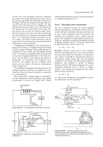
rent for both the load and the voltage coil. This 20.4.4 Three-phase power measurement
method measures the power loss in the load and in For an IZ conductor system the power supplied
the voltage coil. For small load currents the volt- can be measured by n wattmeters if they are con-
age drop in the current coil will be small, there- nected with each wattmeter having its current coil
fore the power loss in this coil will be small and in one of the conductors and its potential coii
the first method of connection introduces little between the conductor and a single common
error. For large load currents the power loss in point. This method of measurement is shown for
the vo!tage coil will be small compared with the both star- and delta-connected three-phase systems
power loss in the load and the second method of in Figures 20.40(a) and (b). The power dissipated
connection is to be preferred. in the three-phase system is given by
Compensated wattmeters of the type shown in
+
Figure 20.38 employ a compensating coil in series P = w, w, + w3
with the voltage windings. This compensating coil Blondel’s theorem states that if the common
is identical to the current coil and tightly wound point for the potential coil is one of the conduc-
with it to produce a magnetic field in opposition
to the main magnetic field due to the load cur- tors then the number of wattmeters is reduced by
one. Thus it is possible to xeasure the power in a
rent. Thus the effect of the voltage coil current is three-phase system using only two wattmeters,
eliminated, and therefore the wattmeter con- irrespective of whether the three-phase system is
nected in the manner shown in Figure 20.38 balanced. This method is shown in Figures
shows no error due to the power consumption 20.41(a) and (b). The phasor diagram for a star-
in the voltage coil. connected balanced load is shown in Figure
For electronic wattmeters the power loss in the
voltage detection circuit can be made to be very 20.41(c). The total power dissipated in the three-
phase system is given by
small and thus the second method of connection
is to be preferred. P= V’, + w,
The current and voltage ranges of wattmeters
can be extended by means of current and voltage i.e., the power dissipated is the algebraic sum of
transformers as shown in Figure 20.39. These the indications on the wattmeters.
7,”:
1”
Compensating W1
coil +nCurrent coil
resistance
Figure 20.38 Compensated dynamometer wattmeter. Current coil (a)
1
(b)
Figure 20.40 (a) Power measurement in a star-
connected three-phase load using three wattmeters; (b)
Figure 20.39 Wattmeter used with instrument power measurement in a delta-connected three-phase load
transformers. using three wattmeters.