
Page 466 - Instrumentation Reference Book 3E
P. 466
Digital voltmeters and digital multimeters 449
low and the power ground. It is available as a
terminal of the input of the instrument. If the
guard is connected to the low of the measurement
circuit then the effect of current flow between the
low terminal and guard is eliminated since they
Time are at the same potential. The potential dividing
action now occurs between the residual leakage
impedance between low and power ground in the
presence of the guard. The value of these leakage
impedances are of order 10"R and 2.5pF. The
d.c. common-mode rejection has now been
I increased to -160dB and the 50Hz comrnon-
i- 156 ps mode rejection to -122dB. Thus a d.c. com-
mon-mode signal of l00V will produce an input
1 ms voltage of 1 pV and a 20-V, 50 Hz common-mode
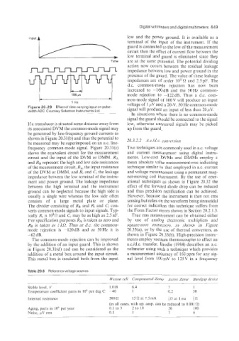
Figure 201.29 Effectof time-varying inputon pulse-
width ADC. Courtesy Solartron Instruments Ltd. signal will produce an input of less than 20 pV.
In situations where there is no common-mode
signal the guard should be connected to the signal
If a transducer is situated some distance away from low, otherwise unwanted signals may be picked
its associated DVM the common-mode signal may up from the guard.
be generated by line-frequency ground currents as
shown in Figure 20.31(b) and thus the potential to 20.3.2.2 A.c./d.c. convetxion
be measured may be superimposed on an a.c. line-
frequency common-mode signal. Figure 20.31(c) Two techniques are commonly used in a.c. voltage
shows the equivalent circuit for the measurement and current measurement using digital instru-
circuit and the input of the DVM or DMM. RA ments. Low-cost DVMs and DMMs employ a
and Rg represent the high and low side resistances mean absolute value measurement-rms indicating
of the measurement circuit, Ri, the input resistance technique similar to that employed in ax. current
of the DVM or DMM, and Ri and Ci the leakage and voltage measurement using a permanent mag-
impedance between the low terminal of the instru- net-moving coil instrument. By the use of oper-
ment and power ground. The leakage impedance ational techniques as shown in Figure 20.32 the
between the high terminal and the instrument effect of the forward diode drop can be reduced
ground can be neglected because the high side is and thus precision rectification can be achieved.
usually a single wire whereas the low side often However, because the instrument is then not rms
consists of a large metal plate or plane. sensing but relies on the waveform being sinusoidal
The divider consisting of RB and Pzi and Ci coii- for correct indication this technique suffers from
verts common-mode signals to input signals. Typ- the Form Factor errors shown in Section 20.2.1.3.
ically Ri is 109R and Ci may be as high as 2.5 nF. True rms measurement can be obtained either
For specification purposes RA is taken as zero and by use of analog electronic multipliers and
Rg is taken as 1 kR. Thus at d.c. the common- square-root extractors. as shown in Figure
mode rejection is -120dB and at 50Hz it is 20.33(a), or by the use of thermal converters, as
-62 dB. shown in Figure 20.33(b). High-precision instru-
The common-mode rejection can be improved ments employ vacuum thermocouples to effect an
by the addition of an input guard. This is shown a.c./d.c. transfer. Brodie (1984) describes an a.c.
in Figure 20.31(d) end can be considered as the voltmeter using such a technique which provides
addition of a metal box around the input circuit. a measurement accuracy of 160 ppm for any sig-
This metal box is insulated both from the input nal level from l00mV to 125V in a frequency
Table 20.6 Weference voltage sources
Ilfestorz cell Compensated Zener Actise Zener Bandgap device
Stable level. I/ 1.018 6.4 I 1
Temperature coefficient parts in lo6 per deg C -40 1 0.3 30
Internal resistance 500 R 15R at 7.5mA at lma
(in all cases, with op. amp. can be reduced to 0.001 0)
Aging, parts in lo6 per year 0.1 to 3 2 to 10 20 100
Noise. LLV rms 0.1 1 I 6