
Page 461 - Instrumentation Reference Book 3E
P. 461
444 Electrical measurements
tl t2 ‘3 t4 t5 t
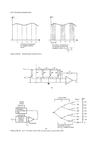
Conversion corresponds Conversion corresponds to
to voltages at sample the average value over the
Doints
integration period, i.e., ‘1 +At
Vin . dt
tl
Figure 20.22 Sampling and integrating ADCs
Input to DAC Input
Result Fs
Parallel
output
ftttt
Successive-
112
logic 100
,01 011
‘1
010
converter
I J 0
Vi n Comparator outputs
(0 if Vi,> output of DAC)
(b)
Figure 20.23 (a) R-2R ladder network DAC; (b) successive -approximation ADC.