
Page 460 - Instrumentation Reference Book 3E
P. 460
Digital voltmeters and digital muhimeters 443
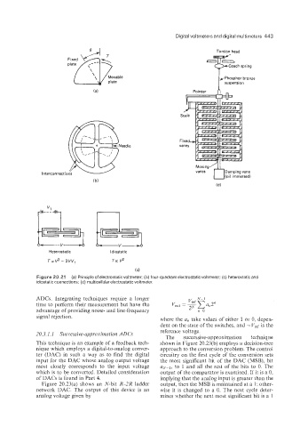
Torsion head
yPhosphor bronze
P
Fixed.
vanes
Moving
vanes Damping vane
(oil immersed)
v1 i
111- - -
Heterostatic ldiostatic
T a v2 - 2vv, To: V2
(C)
Figure 20.21 (a) Principle of electrostatic voltmeter; (b) four-quadrant electrostatic voltmeter; (c) heterostatic and
idiostatic connections; (d) multicellular electrostatic voltmeter.
ADCs. Integrating techniques require a longer
time to perform their measurement but have the
advantage of providing noise- and line-frequency
signal rejection. where the a, take values of either 1 or 0, depen-
dent on the state of the switches, and - Vref is the
20.3.1.1 Sziccessive-uppro.xilnutiorz ADCs reference voltage.
The successive-approximation technique
This technique is an example of a feedback tech- shown in Figure 20.23(b) employs a decision-tree
nique which employs a digital-to-analog conver- approach to the conversion problem. The control
ter (DAC) in such a way as to find the digital circuitry on the first cycle of the conversion sets
input for the DAC whose analog output voltage the most significant bit of the DAC (MSB), bit
most closely corresponds to the input voltage up,-l, to 1 and all the rest of the bits to 0. The
which is to be converted. Detailed consideration output of the comparator is examined. If it is a 0,
of DACs is found in Part 4. implying that the analog input is greater than the
Figure 20.23(a) shows an N-bit R-2R ladder output, then the MSB is maintained at a 1: other-
network DAC. The output of this device is an wise it is changed to a 0. The next cycle deter-
analog voltage given by mines whether the next most significant bit is a 1