
Page 456 - Instrumentation Reference Book 3E
P. 456
Measurement of d.c. and a.c. current and voltage using indicating instruments 439
where E,,, is the voltage transformer turns ratio
given by
EP
la) E,t = -
ns
Figure 20.18(c) shows the phasor diagram of an
actual voltage transformer. The two errors of
voltage transformers are the voltage or ratio error
and the phase-angle error or phase displacement.
The voltage error is defined to be
Rated voitage ratio ( Vp/Vs)
--actual ratio (Vp/ Vs)
x 100%
Actual voltage ratio (P'p/Y,)
The phase displacement is the phase displacement
between the primary and secondary voltages as
shown in Figure 20.18(c), and is positive if the
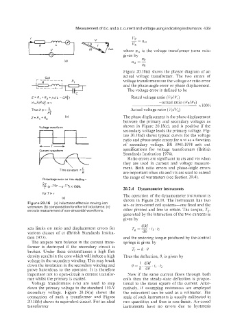
Voltage waveform
secondary voltage leads the primary voltage. Fig-
ure 20.18(d) shows typica: curves for the voltage
ratio and phase angle errors for a vt as a function
of secondary voltage. BS 3941:1974 sets out
-T-
Current waveform specifications for voltage transformers (British
Standards Institution 1974).
Ratio errors are significant in cts and vts when
they are used in current and voltage measure-
'
L
Time constant 7 - ment. Both ratio errors and phase-angle errors
R are important when cts and vts are used to extend
the range of wattmeters (see Section 20.4).
Percentage error on rms reading =
27
- (e-TI27 - e-Tl7) x 100%
T 20.2.4 Dynamometer instruments
for T%T
The operation of the dynamometer instrument is
(C) shown in Figure 20.19. The instrument has two
Figure 20.1 6 (a) Inductance effects in moving-iron air- or iron-cored coil systems-one fixed and the
voltmeters (b) compensation for effect of inductance; (c) other pivoted and free to rotate. The torque, T,,
errors in measurement of non-sinusoidal waveforms
generated by the interaction of the two currents is
given by
dM . .
sets limits on ratio and displacement errors for To = __. 11 . /2
various classes of ct (British Standards Institu- d%
tion 1973). and the restoring torque produced by the control
The ampere turn balance in the current trans- springs is given by
former is destroyed if the secondary circuit is Ts=k.%
broken. Under these circumstances a high flux
density results in the core which will induce a high Thus the deflection, 0, is given by
voltage in the secondary winding. This may break
down the insulation in the secondary winding and
prove hazardous to 1,he operator. It is therefore
important not to open-circuit a current transfor- Now if the same current flows through both
mer whilst the primary is excited. coils then the steady-state deflection is propor-
Voltage transformers (vts) are used to step tional to the mean square of the current. Alter-
down the primary voltage to the standard 110-V natively, if swamping resistances are employed
secondary voltage. Figure 20.1X(a) shows the the instrument can be used as a voltmeter. The
connection of such a transformer and Figure scale of such instruments is usually calibrated in
2O.l8(b) shows its equivalent circuit. For an ideal rms quantities and thus is non-linear. Air-cored
transformer instruments have no errors due to hysteresis