
Page 454 - Instrumentation Reference Book 3E
P. 454
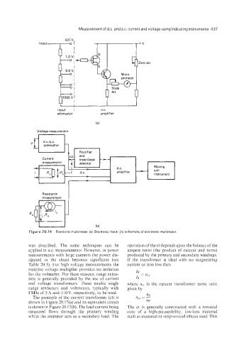
Input   I         d.c.
                         attenuator        amplifier


                Voltage measurement
                 r-----7


                   Resistance
                   measurement


             Figure 20.14  Electronic multimeter. (a) Electronic input; (b) schematic of  electronic multimeter.

             was  described.  The  same  techniques  can  be   operation of the ct depends upon the balance of the
             applied in ax. measurements. However, in power   ampere turns  (the product  of  current  and  turns)
             measurements with large currents the power dis-   produced by the primary and secondary windings.
             sipated  in  the  shunt  becomes  significant  (see   If  the  transformer  is  ideal  with  no  magnetizing
             Table 20.3). For high voltage measurements  the   current or iron loss then
             resistive voltage multiplier provides  no isolation
             for the voltmeter. FQ~ these reasons, range exten-   IP
             sion is generally provided  by  the use  of  current   Is =
             and  voltage  transformers.  These  enable  single   where  nCt is  the  current  transformer  turns  ratio
             range  ammeters  and  voltmeters,  typically  with   given by
             FSDs of 5 A and 110 V, respectively, to be used.   ns
               The principle of the current transformer  (ct) is   nCt = -
             shown in Figure 20.17(a) and its equivalent circuit   np
             is shown in Figure 20.17(b). The load current being   The  ct  is  generally constructed  with  a  toroidal
             measured  flows  through  the  primary  winding   core  of  a  high-permeability,  low-loss  material
             whiist the ammeter acts as a secondary load. The   such as mumetal or strip-wound silicon steel. This