
Page 450 - Instrumentation Reference Book 3E
P. 450
Measurement of d.c. and a.c. current and voltage using indicating instruments 433
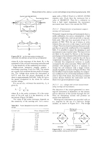
Current-carrying terminals ment with a FSD of lOmA it is l00R/V. If FSD
Four-terminal shunt requires only 10pA then the resistance has a
value of 100,00OR/V. Thus for a voltmeter to
have a high input impedance the instrument
movement must have a low current for FSD.
20.2.1.2 Characteristics ofpermanent magnet-
moving coil instruments
Permanent magnet-moving coil instruments have a
stable calibration, low power consumption, a high
torque-to-weight ratio, and can provide a long uni-
form scale. They can have accuracies of up to 0.1
percent of FSD. With the use of shunts or series
resistors they can cover a wide range ofcurrent and
voltage. Theerrorsdue to hysteresis effectsare small,
and they are generally unaffected by stray magnetic
fields. It is possible to adjust the damping in such
instruments to any required value. The major errors
(b) are likely to be caused by friction in the bearings
Figure 20.10 (a) Ammeter usingarnoving-coil and changes in the resistance of the coil with tempera-
instrument; (b) voltmeter using a moving-coil instrument ture. Copper wire, which is used for the coil, has a
temperature coefficient of +0.4%/K. When used as
where R, is the resistance of the shunt, R, is the a voltmeter this temperature variation is usually
resistance of the coil and swamping resistance and swamped by the series resistance. When used as an
S is the sensitivity of the unshunted movement. ammeter with manganin shunts it is necessary to
High-current ammeters usually employ a swamp the coil resistance with a larger resistor,
movement requiring 15 mA for FSD. The shunts usually manganin, as shown in Figure 20.10(a). This
are usually four-terminal devices made of manga- has the effect of more closely matching the tempera-
nin. The voltage drop across the instrument is ture coefficient of the coillswamp resistance combin-
0.075V and thus the power dissipated in the ation to that of the shunt, thus effecting a constant
shunt is approximately 0.075 IW. Table 20.3 gives current division between the instrument and the
the power dissipation in the shunt for various shunt over a given temperature range.
current ratings.
For use as a d.c. voltmeter the Sensitivity, S,, is
given by 20.2.1.3 A.c. voltage ar?d current measurenzent
using moving-coil instruments
The direction of the torque generated in a mov-
ing-coil instrument is dependent on the instant-
where R, is the series resistance, R is the resist- aneous direction of the current through the coil.
ance of the coil. and S is the sensitivity of the Thus an alternating current will produce no
movement (Figure 20.10(b)). steady-state deflection.
The value of the series resistance depends on Moving-coil instruments are provided with an
the sensitivity of the moving coil. For a move- ax. response by the use of a full-wave bridge
rectifier, as shown in Figure 20.11. The bridge
Table 20.3 Power dissipated in shunt for various current
ratings
Moving-coil
Current (A) Power dissipated ( W) /instrument -\
1 0.075
2 0.150
5 0.375
10 0.75
20 1.50
50 3.15
100 7.50
200 15.00
500 37.50 Ammeter Voltmeter
1000 75.00 Figure 20.11 A.c. current andvoltage measurement
using a rectifier-moving-coil instrument.