Page 465 - Instrumentation Reference Book 3E
P. 465

448  Electrical measurements
                                     Reset  Scaling   20.3.2  Elements in DVMs and DMMs
                                       I   1
                                                     The  ADC is  the  central  element  of  a  DVM  or
                   Voltage to                        DMM. The  ADC  is,  however.  a  limited  input
                                                     range  device  operating  usually  on unipolar  d.c.
                                              Serial
                                             output   signals. Figure 20.30 shows the elements of a com-
                                                     plete DVM or DMM.
                                       Parallel
                      mt a 'in         output
                                                     20.3.2.1  D.c. input stage and guarding
                      -                              ance together with attenuationlamplification  and
                 CL                                  The d.c. input  stage provides high input imped-
                 D       W                           polarity  sensing of  the  signal to ensure that the
                   Number of countsn  a Vi"          voltage  applied  to  the  ADC  is  of  the  correct
                                                     magnitude and polarity.
            Figure 20.27  Pulse-width ADC.
                                                       DVMs and DMMs are often used to measure
                                                     small d.c. or a.c. signals superimposed on much
            Table 20.6 (taken  from Spreadbury  1981) com-   larger  common-mode  signals.  For  example,  in
            pares  the  characteristics  of  these  two  types  of   measuring the  output signal from a  d.c. Wheat-
            Zener  devices  with  bandgap  devices  and  the   stone  bridge,  as  shown  in  Figure  20.31(a),  the
            Weston standard cell.                    common-mode voltage is half the bridge supply.

                                      tv


                                                    Up gate


                                                                             Counter


                                                   Down gate
                                                                             Display

                                                                  Integration time
                                      -V
                -
                                            r          Reference


                          /'
                n
                   UP
                          -  1       UP     UP
                       Count

                       down                   (b)
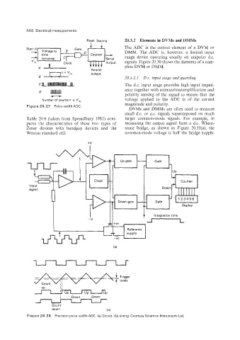
             Figure 20.28  Precision pulse-width ADC. (a)  Circuit; (b) timing. Courtesy Solartron Instruments Ltd.
   460   461   462   463   464   465   466   467   468   469   470