
Page 557 - Instrumentation Reference Book 3E
P. 557
Electronics 539
Polyethylene indeed this is often done for dedicated systems
sphere in industry-the more usual system is to incorp-
orate a series of interconnecting individual circuits
into a common frame. This permits a variety of
arrangements to be made by plugging in the
required elements into this frame. which generaliy
also provides the necessary power supplies. This
"building-block" system has become standardized
worldwide under the title of NIM and is based on
the U.S. Nuclear Regulatory Commission
Aluminum Perspex (USNRC) Committee on Nuclear Instrument
6Lil (EU) light-tight light guide Modules, presented in USNRC Piibiication T'D-
crystal shield
Figure 22.14 sphere fast-neutron detector. 20893. The basic common frame is 483mm (19
in.) wide and the plug-in units are of standard
between 10 and 30cm to cover the whole energy dimensions, a single module being 221 mm
range. high x 34.4mm wide x 250mm deep (excluding
For thermal neutrons (E = 0.025 eV) an inter- the connector). Modules can be in widths of
a) or
mediate reaction such as 6Li(~~, "B(n, 01) or one, two, or more multiples of 34.4mm. Most
fission can be used, a solid-state detector being standard units are single or double width. The
employed to count the secondary particles emitted rear connectors which plug into the standard
in the reaction. For fast neutrons a radiator in NIM bin have a standardized arrangement for
which[ the neutrons produce recoil protons can be obtaining positive and negative stabilized sup-
mounted close to a solid-state detector, and the plies from the common power supply, which is
detector counts the protons. By sandwiching a thin mounted at the rear of the NIM bin. The use of a
layer of 6LiF between two solid-state detectors and standardized module system allows the use of
summing the coincident alpha and tritium pulses units from a number of different manufacturers
to give an output signal proportional to the energy in the same bin, since it may not be possible or
of the incident neutron plus 4.78MeV, the economic to obtain all the units required from
response of the assembly with respect to incident one supplier. Some seventy individual modules
neutr'on energy was found to be nearly linear. are available from one manufacturer, which gives
some idea of the variety.
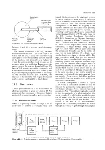
A typical arrangement is shown in Figure
22.3 Electronics 22.15, where a scintillation counter is used to
measure the gamma-ray energy spectrum from a
A more general treatment of the measurement of small source of radioactivity. The detector could
electrical quantities is given in Chapter 20. We consist of a NaI (Tl) scintillator optically coupled
concentrate here on aspects of electronics that are to the photocathode of a photomultiplier, the
particularly relevant to nuclear instrumentation. whole contained in a light-tight shielded enclos-
ure of metal, with the dynode resistor chain
22.3.11 Electronics assemblies feeding each of the dynodes (see Section 21.3.1)
located in the base of the photomultiplier,
Whilst it is perfectly feasible to design a set of together with a suitable preamplifier to match
electronics to perform a particular task-and the high-impedance output of the photomultiplier
n n
/
Shield for I
detector I
assern bly
I
L J
Figure 22.1 5 Typical arrangement of electronics. SC: scintillator; PM: photomultiplier; PA: preamplifier