
Page 559 - Instrumentation Reference Book 3E
P. 559
Elecaronics 541
Figure 22.21 improved stabilizer.
ler. Such a circuit is shown in Figure 22.21, where former; to convert the high impedance of most
the sensing element, the transistor TR3, compares detector outputs to a sufficiently low impedance
a fraction of the output voltage which is applied which would match a 50- or 70-R connecting
to its base with the fixed Zener voltage. Through cable. If the detector is a scintillating counter,
the series control transistor TR4, the difference the output impedance of the photomultiplier is
amplifier TR1, TR3 and TR2, corrects the rise or of the order of several thousand ohms, and
fall in the output voltage which initiated the con- there would be almost complete loss of signal
trol signal. if one coupled the output of the counter directly
to the 504 impedance of the cable-hence the
necessity of providing a suitable impedance
22.32. J High-voltcrge power supplies
matching device.
High voltages are required to operate photomul-
tipliers, semiconductor detectors, multi- and single- 22.3.4 Scalers
wire gas proportional counters, etc., and their
output must be as stable and as free of pulse From the earliest days it has been the counting of
transiients as possible. For photomultipliers the nuclear events which has been the means of
stability requirements are extremely important, demonstrating the decay of radioactive nuclei.
since a variation in overall voltage across a Early counters used thermionic valves in scale-
photomultiplier of, say, 0.1 percent can make of-two circuits, which counted in twos. By using
a 1 percent change in output. For this reason a series of these, scale-of-ten counters may be
stabilities of the order of 0.01 percent over the derived. However, solid-state circuits have now
range of current variation expected and 0.001 reduced such scale-of-ten counters to a single
percent over mains a.c. supply limits are typically semiconductor chip, which is far more reliable
required in such power supplies. than the thermionic valve systems and a fraction
of the sue and current consumption.
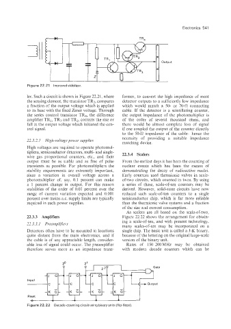
As scalers are all based on the scale-of-two,
22.33 Amplifiers Figure 22.22 shows the arrangement for obtain-
ing a scale-of-ten. and with present technology,
22.3.3. I Preamplifiers
many scales-of-ten may be incorporated on a
Detectors often have to be mounted in locations single chip. The basic unit is called a J-K binary,
quite distant from the main electronics, and if because of the lettering on the original large-scale
the cable is of any appreciable length, consider- version of the binary unit.
able Loss of signal could occur. The preamplifier Rates of 150-200MHz may be obtained
therefore serves more as an impedance trans- with modern decade counters which can be
2’
2’
Input
Input
-
-
Reset
Reset
-0-
-0-
Figure 22.22 Decade-counting circuit using binary units (flip-flops).
Figure 22.22 Decade-counting circuit using binary units (flip-flops).