
Page 558 - Instrumentation Reference Book 3E
P. 558
The main amplifier raises the amplitudes of the 311 E\
540 Nuclear instrumentation technology
to the lower input impedance of the main pulse
amplifier, generally of the order of 50 Sl. This also
allows the use of a relatively long coaxial cable to
couple the detector to the electronics if necessary.
input pulses to the range of about 0.5-1OV. The
single-channel analyzer can then be set to cover a
range of input voltages corresponding to the Figure 22.1 6 Full-wave rectifier.
energies of the source to be measured. If the
energy response of the scintillator-photomulti-
plier is linear-as it is for NaI (T1)-then the
system can be calibrated using sources of known
energies, and an unknown energy source can be
identified by interpolation.
22.3.2 Power supplies
The basic power supplies for nuclear gauging Figure 22.17 Bridgerectifier.
instruments are of two classes: the fist supplies
relatively low d.c. voltages at high currents 3II[$ :: 4
(e.g., 5-30V at 0.5-50A) and the second high volt-
ages at low currents (e.g., 200-5OOOV at 200pA
-5 mA). Alternatively, batteries, both primary
and secondary (i.e., rechargeable) can be used for
portable instruments. In general, for laboratory
use d.c. supplies are obtained by rectifying and Figure 22.1 8 Voltage-doubling circuit
smoothing the mains a.c. supply. In the UK and
most European countries the mains as. power sup-
ply is 50Hz, while in the United States and South
America it is 60Hz, but generally a supply unit
Iron-cored
designed for one frequency can be used on the other. choke
However, mains-supply voltages vary considerably,
being 240V in the UK and 220V in most of the High-value
EEC countries, with some countries having supplies
of 110, 115, 120, 125. 127, etc. The stability of some
of these mains supplies can leave much to be Figure 22.19 Smoothing filter.
desired, and fluctuations of plus and minus 50V
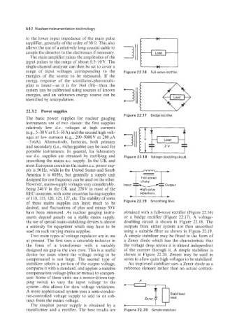
have been measured. As nuclear gauging instru- obtained with a full-wave rectifier (Figure 22.16)
ments depend greatly on a stable mains supply, or a bridge rectifier (Figure 22.17). A voltage-
the use of special mains-stabilizing devices is almost doubling circuit is shown in Figure 22.18. The
a necessity for equipment which may have to be outputs from either system are then smoothed
used on such varying mains supplies. using a suitable filter as shown in Figure 22.19.
Two main types of voltage regulator are in use A simple stabilizer may be fitted in the form of
at present. The first uses a saturable inductor in a Zener diode which has the characteristic that
the form of a transformer with a suitably the voltage drop across it is almost independent
designed air gap in the iron core. This is a useful of the current through it. A simple stabilizer is
device for cases where the voltage swing to be shown in Figure 22.20. Zeners may be used in
compensated is not large. The second type of series to allow quite high voltages to be stabilized.
stabilizer selects a portion of the output voltage, An improved stabilizer uses a Zener diode as a
compares it with a standard, and applies a suitable reference element rather than an actual control-
compensation voltage (plus or minus) to conipen-
sate. Some of these units use a motor-driven tap-
ping switch to vary the input voltage to the R
system-this allows for slow voltage variations.
A more sophisticated system uses a semi-conduc-
tor-controlled voltage supply to add to or sub-
tract from the mains voltage.
The simplest power supply is obtained by a
transformer and a rectifier. The best results are Figure 22.20 Simple stabilizer.