
Page 563 - Instrumentation Reference Book 3E
P. 563
Electronics 545
2.3.6.4 Coincidence and mti-coincidence cir- The use of coincidence circuits arose as a result
cuits of studies of cosmic rays, since it allowed a series
of counters to be used as a telescope to determine
A coincidence circuit is a device with two or more the direction of path of such high-energy parti-
inputs which gives an output signal when all the cles. By the use of highly absorbing slabs between
inputs occur at the same time. These circuits have counters, the nature and energies of these cosmic
a finite resolving time-that is, the greatest inter- particles and the existence of showers of simuita-
val of time r which may elapse between signals neous particles were established. The anticoinci-
for the circuit still to consider them coincident. dence circuit was used in these measurements to
Figure 22.30 shows a simple coincidence circuit
wherle diodes are used as switches. If either or determine the energies of particles which were
absorbed in dense material such as lead, having
both diodes are held at zero potential then the triggered a telescope of counters before entering
relevant diode or diodes conduct and the output the lead, but not triggering counters below the
of the circuit is close to ground. However, if both lead slab.
inputs are caused to rise to the supply voltage Nowadays coincidence circuits are used with
level V, by simultaneous application of pulses of detectors for the products of a nuclear reaction
height V,, then both diodes cease to conduct, and
the output rises to the supply level for as long as or particles emitted rapidly in cascade during
radioactive decay or the two photons emitted in
the input pulses are present. An improved circuit
is shown in Figure 22.31. the annihilation of a positron. The latter phenom-
enon has come into use in the medical scanning
and analysis of human living tissue by computer-
activated tomography (CAT-scanning).
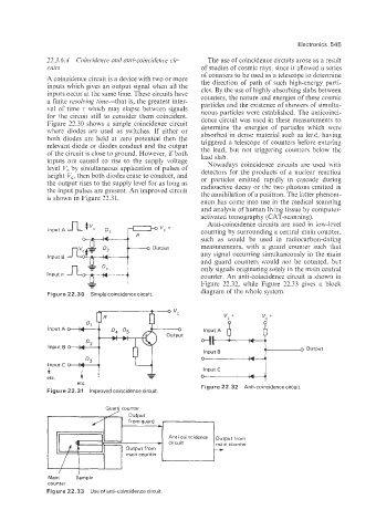
Anti-coincidence circuits are used in low-level
Input A counting by surrounding a central main counter,
such as would be used in radiocarbon-dating
measurements, with a guard counter such that
any signal occurring simultaneously in the main
Input B
and guard counters would not be counted, but
only signals originating solely in the main central
Input n counter. An anti-coincidence circuit is shown in
- Figure 22.32, while Figure 22.33 gives a block
Figure 22.30 Simple coincidence circuit. diagram of the whole system.
D. O D 0 vc vc +
Input A
output
lnpuit B output
u
4
-
etc. ;“puit if i
etc.
Figure 22.31 Improved coincidence circuit Figure 22.32 Anti-coincidence circuit
Guard counter
Main Sample
counter
Figure 22.33 Use of anti-coincidence circuit