
Page 561 - Instrumentation Reference Book 3E
P. 561
Electronics 543
In
Q--
CRO
Figure 22.25 Blockdiagram of rnultichannelanalyzer.
give nearly 1 percent change of output. The
mean current taken by the chain is small. and
the fitting of bypass capacitors allows pulses of
current higher in value than the standing current
to be supplied to the dynodes, particularly those
close to the anode where the multiplied electron
cascade, which started from the photocathode,
Figure 22.26 Principle of Willtinson ADC using linear has now become a large number due to the
discharge of a capacitor. multiplication effect. However, as the number
of pulses to be counted becomes more than
allow the electrons ejected by the scintillator about 15,000-50,000 per second. it is necessary
light flash to be accelerated and multiplied at to increase the standing current through the
each dynode. For counting rates up to about lo5 dynode chain. Otherwise space charge effects
per second, the resistors are usually equal in cause the voltages on the dynodes to drop, so
value and high resistance. so that the total cur- reducing the gain in the photomultiplier. When
rent taken by the chain of resistors is of the the counting rate to be measured is high, or very
order of a few hundred microamperes. Figure fast rise times have to be counted, then the
22.2’1 shows a typical dynode resistor chain. As dynode current may have to be increased
has ,already been pointed out, the high voltage from a few hundred microamperes to some
supplying the dynode chain must be extremely 5-10MA, and a circuit as shown in Figure
stable and free from voltage variations, spurious 22.28 is used. Photomultipliers are also discussed
pulses, etc. A 0.1 percent change in voltage may in Chapter 21.
-
-
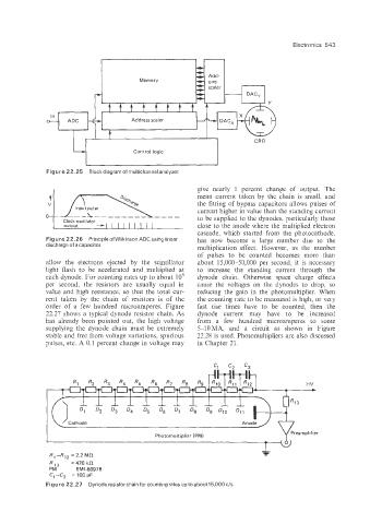
R1--RI2 = 2.2 Mi2
RIc3 =470 k.Q
PM EM 1-60976
C, --C3 = 100 PF
Figure 22.27 Dynode resistor chain for counting rates up to about15,OOO c/s.