
Page 560 - Instrumentation Reference Book 3E
P. 560
542 Nuclear instrumentation technology
Pulse from
detector
Counter
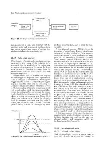
Figure 22.23 Single-channel pulse-height analyzer.
incorporated on a single chip together with the produces an output pulse. A V is called the chan-
auxiliary units, such as standard oscillator, input nel width.
and output circuits, and means of driving light A multichannel analyzer (MCA) allows the
displays to indicate the count achieved. separation of pulses from a detector into channels
determined by their amplitudes. Early analyzers
used up to twenty or more single-channel anal-
22.3.5 Pulse-height analyzers yzers set to successively increasing channels.
These, however, proved difficult to stabilize, and
If the detector of nuclear radiation has a response the introduction of the Hutchinson-Scarrott sys-
governed by the energy of the radiation to be tem of an analog-to-digital converter (ADC)
measured then the amplitude of the pulses from combined with a computer memory enabled more
the detector is a measure of the energy. To deter- than 8000 channels to be provided with good
mine the energy, therefore, the pulses from the stability and adequate linearity. The advantages
detector must be sorted into channels of increas- of the MCA are offset by the fact that the dead
ing pulse amplitude. time (that is, the time during which the MCA is
Trigger circuits have the property that they can unable to accept another pulse for analysis) is
be set to trigger for all pulses above a preset level. longer than that of a single-channel analyzer
This is acting as a discriminator. By using two and so it has a lower maximum counting rate. A
trigger circuits, one set at a slightly higher trigger- block diagram of a typical multichannel analyzer
ing level than the other. and by connecting the is shown in Figure 22.25. The original ADC was
outputs to an anti-coincidence circuit (see Section that of Wilkinson, in which a storage capacitor is
3.3.6.4), the output of the anti-coincidence circuit first charged up so that it has a voltage equal to
will be only pulses which have amplitudes falling the peak height of the input pulse. The capacitor,
within the voltage difference between the trigger- is then linearly discharged by a constant current,
ing levels of the two discriminators. Figure 22.23 so producing a ramp waveform, and during
shows a typical arrangement and Figure 22.24 this period a high-frequency clock oscillator is
shows how an input pulse 1, below the triggering switched on (Figure 22.26). Thus the period of
level V. produces no output, nor does pulse 3, the discharge and the number of cycles of the
above the triggering level V + A V. However, clock are proportional to the magnitude of the
pulse 2, falling between the two triggering levels, input pulse. The number of clock pulses recorded
during the ramp gives the channel number, and
after counting these in a register the classification
Voltage level I can be recorded, usually in a ferrite-core memory.
1 approximation analog-to-digital converter, due
A later development is the use of the successive
to Gatti, Kandiah, etc., which provides improved
n
3
channel stability and resolution. ADCs are
further discussed in Chapter 20.
22.3.6 Special electronic units
22.3.6.1 D.ynode resistor chains
Time- Each photomultiplier requires a resistor chain to
Figure 22.24 Waveforms and operation of Figure 22.23. feed each dynode an appropriate voltage to