
Page 148 - Integrated Wireless Propagation Models
P. 148
126 C h a p t e r T h r e e
Morphology
type I
Measurement integration:
extract morphology specific
data and derive
��Y i Slope
: slope �
' '
' '
Area
impacted by
morphology
In tercept Radial distance
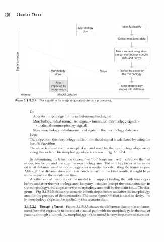
FIGURE 3.1.5.2.4 The algorit m for morphology/attribute data processing.
h
Do
Allocate morphology for the radial-normalized signal
Morphology-radial-normalized signal = (measured-morphology-signal)
(predicted-nonmorphology signal)
Store morphology-radial-normalized signal in the morphology database
Done
The slope from the morphology-radial-normalized-signal is calculated by using the
best-fit algorithm
The slope is stored for this morphology and used for the morphology-slope array
along this radial. This morphology slope is shown in Fig. 3.1.5.2.4.
In determining the transition slopes, two "for" loops are used to calculate the two
slopes, one before and one after the morphology area. The only key factor is to decide
on what distance from the morphology area is needed for calculating the transit slopes.
Although the distance does not have much impact on the final results, it might have
some impact on the calculation time.
Another added flexibility of the model is to support finding the path loss slopes
before and after the morphology area. In many instances (except the water situation in
the morphology), the slope after the morphology area will be the main issue. The dia
gram in Fig. 3.1.5.2.5 shows the scenario of both slopes before and after the morphology
area for the purpose of demonstration. The same algorithm that is used to derive the
in-morphology slope can be applied in this scenario also.
2
3.1.5. . 1 Through a Tunnel Figure 3.1.5.2.5 shows the difference due to the enhance
ment from the beginning to the end of a radial path with the morphology. In the case of
passing through a tunnel, the morphology of the tunnel is very important to consider.