Page 146 - Integrated Wireless Propagation Models
P. 146

124    C h a p t e r   T h r e e


                                    In tercept    Slope


                                               Radial distance
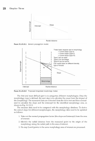
               FIGURE 3.1.5.2.1  Generic propagation mod l.
                                                e
                                                      Three basic impacts due to morphology
                                                           < current slope (type I)
                           I                               = c urrent slope (type II)
                                                           >current slope (type )
                                                                           l
                                                                          l
                                                                          I
                                                      Type I can be water
                            -·
                                                          I

                                                           I
                           : · · ·· ·· ······         Type can be foliage
                                 -··
                                                      Type  can be tunnel
                                                           l
                                                           l
                                                          I
                     .r:          · ·
                     c,                               Can varies base on different density,
                     c
                     �     I                          type of forests
                     1ii
                     Cii   I                                     .. .
                     c                              --- ----···  · ·· .. ... .
                     Cl                                                ..
                     Ui    I                              ::�: ;    . .  ·
                                                                         -
                           I                                         .  · ....
                                                                         -
                           I
                                          Morphology
                           I
                        In tercept             Radial distance
               FIGURE 3.1.5.2.2  Proposed integrated morphology mode l.
                  The first and most difficult part  s   t o   categorize different morphologies. Once the
                                              i
               morphology type is defined, the next step is to calculate the cause from the impact of
               the morphology. The measured data are extracted from the drive test and then normal­
               ized to calculate the slope and the intercept for the identified morphology area, as
               shown in Fig. 3.1.5.2.3.
                  The measure data need to be compared with the morphology database. To derive
               the correct slope for different morphologies, the morphology data need to be updated
               as follows:
                    1. Take out the normal propagation factor (the slope and intercept) from the area
                      of interest.
                    2. Identify the  radial distance  from the measured point to  the  origin of the
                      morphology along the radial path in the area of interest.
                    3. Do step 2 until points in the same morphology area of interest are processed.
   141   142   143   144   145   146   147   148   149   150   151