
Page 151 - Integrated Wireless Propagation Models
P. 151
M a c r o c e l l P r e d i c t i o n M o d e l s - P a r t 2 : P o i n t - t o - P o i n t M o d e l s 129
The chart of the diffraction loss L versus the diffraction parameter V is shown in
v
1
Fig. . 9.2.2.1.2, but the diffraction parameter i s replaced by V for calculating the inte
grated diffraction loss, which needs to include the factor of morphology I attributes:
• Use of the diffraction loss curve (diffraction loss (L) versus normal diffraction
parameter v) for finding the terrain diffraction loss. The height of edge h is
P
used. Therefore, H = h .
P
• Use of the diffraction loss curve for finding the morphology diffraction loss.
The morphology loss L(V _morphology) = L(V), where the new diffraction
parameter V can be found from the diffraction loss curve for H = h + a. The
P
knife-edge height H is increased by the morphology of additional height, as
shown in Fig. 3.1.5.2.8.
The figure of morphology diffraction loss curve is the same as the figure of
1
terrain diffraction loss curve, as shown in Fig. . 9.2.2.1.2.
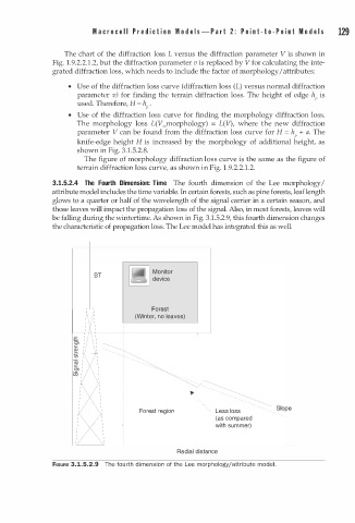
3.1.5.2.4 The Fourth Dimension: Time The fourth dimension of the Lee morphology I
attribute model includes the time variable. In certain forests, such as pine forests, leaf length
glows to a quarter or half of the wavelength of the signal carrier in a certain season, and
those leaves will impact the propagation loss of the signal. Also, in most forests, leaves will
be falling during the wintertime. As shown in Fig. 3.1.5.2.9, this fourth dimension changes
the characteristic of propagation loss. The Lee model has integrated this as well.
fr.l Monitor
BT � device
Forest
(Winter, no leaves)
Forest region Less loss Slope
(as compared
with summer)
Radial distance
FIGURE 3.1.5.2.9 The fo rth dimension of the Lee morphology/attribute mode. l
u