
Page 149 - Integrated Wireless Propagation Models
P. 149
M a c r o c e l l P r e d i c t i o n M o d e l s - P a r t 2 : P o i n t - t o - P o i n t M o d e l s 127
Transition
slopes
Morphology
type I
Measurement integration:
extract morphology specific
Slope data and derive
Morphology
slope
Area
impacted by
morphology
In tercept Radial distance
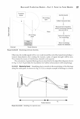
FIGURE 3.1.5.2.5 Morphology/attribute flexibility.
Otherwise, the mobile signal will be very weak toward the end of the turmel (morphology =
tunnel). Immediately after existing the tunnel, a spike of signal strength will be seen.
This creates the issues of interference, handoff, and capacity.
The calculation of generic blockage loss is described in the algorithm diagram shown
in Fig. 3.1.5.2.5. It provides the foundation for further enhancement with morphology.
3.1.5.2.2 Blocked by Forest Something else to consider is the morphology of the blockage
along the radio path. As shown in Fig. 3.1.5.2.6, a simple example of blockage is a forest.
BTS
... . · · · · · ·
....
·····
· · · · ·
c
0
i
[iJ
Radial distance
FIGURE 3.1.5.2.6 Handling of a special case.