
Page 147 - Integrated Wireless Propagation Models
P. 147
M a c r o c e l l P r e d i c t i o n M o d e l s - P a r t 2 : P o i n t - t o - P o i n t M o d e l s 125
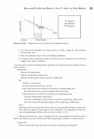
Intercept Radial distance
FIGURE 3.1.5.2.3 In tegrated results for different morphologies/attributes.
4. Use the best-fit algorithm for these points to yield a slope in each different
morphology area.
5. Store the multiple slopes in the morphology database.
6. Compare with the previous slope in the same area of interest and set the time
trigger if the slope is different.
A pseudocode is used to implement this algorithm for storing the measurement data, as
shown below:
Preparation
Allocate all radial paths
Allocate morphology slope array
Allocate all data points along a specific radial path
Do
Allocate a radial array
Get the radial distance from cell site
If the data point is not within the boundary of morphology area
Store the measured signal strength in the radial array
If the data point is within the boundary of morphology area
Allocate morphology radial array
Get the morphology radial distance from the morphology origin point
Store the measured signal strength in the morphology radial array
Done
The slope and intercept for the radial arrays are calculated by the best-fit algorithm
Then store the slope and intercept of each radial path. The algorithm for the pro
cess of morphology I attribute data is shown in Fig. 3.1.5.2.4
A different pseudocode, used to implement the measurement integration and to
derive the slope in an area of interest for the morphology I attribute, is shown below:
Preparation
Allocate all morphology data point along the morphology radial path