
Page 270 - Integrated Wireless Propagation Models
P. 270
248 C h a p t e r F o u r
50
�
60
�
70
�
ill 80 '
:s. I ' �
CIJ 90
CIJ \
0 \
� 1 0 0
'-
Cii
c... 1 1 0
'
1 2 0 '
1 3 0
1 4 0
50 1 0 0 1 0 00
Path distance (m)
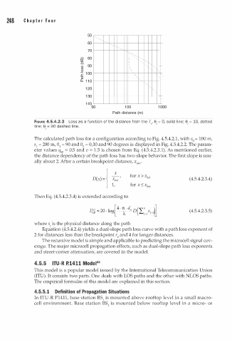
FIGURE 4.5.4.2.2 Loss as a function of the distance from the Tx' e 0, solid line; e 10, dotted
=
=
, ,
line; e 90 dashed line.
=
,
The calculated path loss for a configuration according to Fig. 4.5.4.2.1, with s0 = 100 m,
s 1 = 200 m, 0 1 = 90 and 0 = 0,10 and 90 degrees is displayed in Fig. 4.5.4.2.2. The param
2
eter values q90 = 0.5 and v = 1.5 is chosen from Eq. (4.5.4.2.3.1). As mentioned earlier,
the distance dependency of the path loss has two-slope behavior. The first slope is usu
ally about 2. After a certain breakpoint distance, x '
brk
D(x) =J x: k ' for x > x brk ( 4.5.4.2.3.4)
1 1, for x � x brk
Then Eq. (4.5.4.2.3.4) is extended according to
L < = 20 log[ 4 n d" o ( "' " s . )l (4.5.4.2.3.5)
"J
-
· -
£...j=l J-1 �
dB
A
where i is the physical distance along the path
s
Equation (4.5.4.2.4) yields a dual-slope path loss curve with a path loss exponent of
2 for distances less than the breakpoint r and 4 for longer distances.
b
The recursive model is simple and applicable to predicting the microcell signal cov
erage. The major microcell propagation effects, such as dual-slope path loss exponents
and street-corner attenuation, are covered in the model.
4.5.5 IT - R P. 1 4 1 1 Model44
U
This model is a popular model issued by the International Telecommunication Union
(ITU). It consists two parts. One deals with LOS paths and the other with NLOS paths.
The empirical formulas of this model are explained in this section.
4.5.5. 1 Definition of Propagation Situations
In ITU-R P1411, base station BS1 is mounted above rooftop level in a small macro
cell environment. Base station BS is mounted below rooftop level in a micro- or
2