Page 267 - Integrated Wireless Propagation Models
P. 267

M i c r o c e l l   P r e d i c t i o n   M  o d e l s    245


                                        0 -
                                       -10
                                      -20 -
                                   ((}  -30 -
                                   "0
                                   ui  -40 -         �
                                   en
                                   .2   -50 -        �
                                   (ij
                                   c                 �
                                   Ol  -60 -
                                   i:i5              �
                                      -70 -
                                      -80 -
                                                     �
                                      -90 .
                                      -100        I   rb
                                                     I I
                                         0  75  1 5 0  225  300  350
                                                      r, m
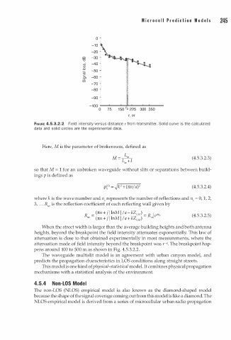
               FIGURE 4.5.3.2.2  Field intensity versus distance r from transmitter. Solid curve is the calculated
               data and solid circles are the experimental data.


                  Here, M is the parameter of brokenness, defined as
                                               M = �                            (4.5.3.2.3)
                                                   Lm +l
               so that M = 1 for an unbroken waveguide without slits or separations between build­
               ings p is defined as

                                                                                ( 4.5.3.2.4)

               where k is the wave number and n, represents the number of reflections and n,  = 0, 1, 2,
                 .
               3,  . .   R11,  is the reflection coefficient of each reflecting wall given by
                                    R  =  (rcn +   j l lnM  I /a - kZ )  =  lr.>  l e i'fi,   (4.5.3.2.5)
                                                         EM
                                          n +
                                                    a + k
                                     "
                                     '  (rc  j l lnM I /  Z )   f'"'
                                                         EM
                  When the street width is larger than the average building heights and both antenna
               heights, beyond the breakpoint the field intensity attenuates exponentially. This law of
               attenuation is close to that obtained experimentally in most measurements, where the
                                                                     q
               attenuation mode of field intensity beyond the breakpoint was  - . The breakpoint hap­
                                                                    ,
                                   m
               pens around 100 to 500  a s shown in Fig. 4.5.3.2.2.
                  The waveguide multislit model is in agreement with urban canyon model, and
               predicts the propagation characteristics in LOS conditions along straight streets.
                  This model is one kind of physical-statistical model. It combines physical propagation
               mechanisms with a statistical analysis of the environment.
               4.5.4  Non-LOS Model
               The non-LOS (NLOS) empirical model is also known as the  diamond-shaped model
               because the shape of the signal coverage coming out from this model is like a diamond. The
               NLOS empirical model is derived from a series of microcellular urban radio propagation
   262   263   264   265   266   267   268   269   270   271   272