
Page 262 - Integrated Wireless Propagation Models
P. 262
240 C h a p t e r F o u r
4.5.2.2 Kaji and Akeyama Microcellular Model
In this model, two dominant waves are considered: the waves that propagate over the
tops of buildings and the waves that propagate along road paths. They are called row
waves: "building diffracted waves" (BD waves) and the along-road path (RG).
BD waves propagate in all directions, while RG waves propagate in a linear fashion
like plant roots. The total received power is the summation of received power from both
.
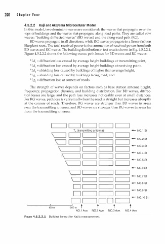
BD waves and RG waves. The building distribution in test area is shown in Fig. 4.5.2.2 1 .
B
Figure 4.5.2.2.2 shows the following excess path losses for D waves and RG waves:
*Ld1 = diffraction loss caused by average height buildings at transmitting point,
*Ld 2 = diffraction loss caused by average height buildings at receiving point,
*Ld3 = shielding loss caused by buildings of higher than average height,
*Lg1 = shielding loss caused by buildings facing road, and
*Lg 2 = diffraction loss at corners of roads.
The strength of waves depends on factors such as base station antenna height,
frequency, propagation distance, and building distribution. For BD waves, diffrac
tion losses are large, and the path loss increases noticeably even at small distances.
For RG waves, path loss is very small when the road is straight but increases abruptly
at the corners of roads. Therefore, RG waves are stronger than BD waves in areas
near the transmitting antenna, and BD waves are stronger than RG waves in areas far
from the transmitting antenna .
._______,I .__ I ____.I I I .__ I _ __J I .__ I ----�
Tx (transmitting antenna) - N0.1 St
\ I I ,...--'------., ...________,
- N0.2 St
c=J I.________. .____ _ ____. ...___ _ __, ._ _ _ __,
- N0.3 St
\.___ _ _ ___.
- N0.4 St
\.___ _ ____.
- N0.5 St
\.___ _ __,
- N0.6 St
c=J
- N0.7 St
0
- N0.8 St
D
- N0.9 St
D I
.__ _____.
.
- N0 1 0 St
I
CJ ...._______. D D .__ _____.
'-- - - - ----' 1 0 _ 0_ m _ _ _ __, 200 m t t t 1
N0.1 Ave. N0.2 Ave. N0.3 Ave. N0.4 Ave.
FIGURE 4.5.2.2.1 Building lay out for Ka i ' s measurement.
j