
Page 257 - Integrated Wireless Propagation Models
P. 257
M i c r o c e l l P r e d i c t i o n M o d e l s 235
The value of this correction is the loss proportional to the length of the radio path
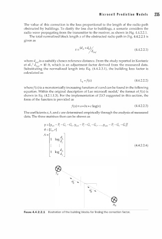
obstructed by buildings. To clarify the loss due to buildings, a scenario considers the
radio wave propagating from the transmitter to the receiver, as shown in Fig. 4.4.2.2.1.
The total normalized block length x of the obstructed radio path in Fig. 4.4.2.2.1 is
given as
( 4.4.2.2.1)
where d8,e1 is a suitably chosen reference distance. From the study reported in Kostanic
et al./ d Bref = 10 ft, which is an adjustment factor derived from the measured data.
Substituting the normalized length into Eq. (4.4.2.3.1), the building loss factor is
calculated as
L = f(x) (4.4.2.2.2)
B
where f (x) is a monotonically increasing function of x and can be found in the following
equation. Within the original description of Lee microcell modeV the format of f(x) is
2
shown in Eq. (4. . 1 . 1 . 3). For the implementation of JLO suggested in this section, the
form of the function is provided as
f(x) = a+ bx+c log(x) ( 4.4.2.2.3)
The coefficients a, b, and c are determined empirically through the analysis of measured
data. The three matrixes then can be shown as
( 4.4.2.2.4)
Rx
FIGURE 4.4.2.2.1 I l l u stration of the building blocks for finding the correction factor.