
Page 266 - Integrated Wireless Propagation Models
P. 266
244 C h a p t e r F o u r
z
u
i
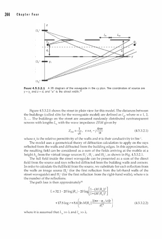
FIGURE 4.5.3.2.1 A 2D diagram of the waveg i de n the zy plan. The coordinates of source are
2
y = y1 and z = d, and "a" is the street width. 8
Figure 4.5.3.2.1 shows the street in plain view for this model. The distances between
the buildings (called slits for the waveguide model) are defined as 1"', where m = 1, 2,
3, . . . . The buildings on the street are assumed randomly distributed nontransparent
screens with lengths L"' with the wave impedance ZEM given by
1 . ; -- 4ncr
ZEM = r:: ' £ = £ , - (4.5.3.2.1)
-.;£ (!)
1
where £, is the relative permittivity of the walls and cr is their conductivity in Sm- •
The model uses a geometrical theory of diffraction calculation to apply on the rays
reflected from the walls and diffracted from the building edges. In this approximation,
the resulting field can be considered as a sum of the fields arriving at the mobile at a
height h"' from the virtual image sources II/, II 1 -, and II/, as shown in Fig. 4.5.3.2.1.
The full field inside the street waveguide can be presented as a sum of the direct
field from the source and rays reflected diffracted from the building walls and corners.
In order to calculate the full field from the source, we substitute for each reflection from
the walls an image source Tin+ (for the first reflection from the left-hand walls of the
street waveguide) and Tin- (for the first reflection from the right-hand walls), where n is
the number of the reflections.
2
The path loss is then approximately 8
[ - ( M IR 1 ) 2]
1
/1
- 32.1- 2 0 log IR�� I - 2 0 log
L - 2
1 + ( M IR" I)
[(nn-�,la)]r l
+1 7 .8 log r+ 8.6�lnMIR" I I ; (4.5.3.2.2)
� p/1 )
where it is assumed that L >> A and l >> A.
m m