
Page 263 - Integrated Wireless Propagation Models
P. 263
I
M i c r o c e I P r e d i c t i o n M o d e I s 241
,'D - - - - - - - [LdJ - l- - - - - - ,•- Average
-
-
¢�1 r I l i � \ �:�:,,
/ as as �
...,__ - - - - - - - 1 �;: � - - - - - - - - � � Receiving
-
Transmitting � _ _ _
antenna 1 antenna
RG waves
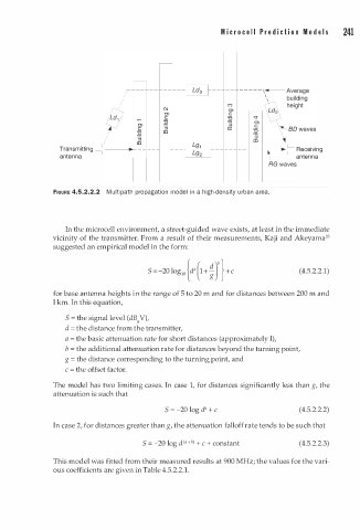
FIGURE 4.5.2.2.2 M u l ti path propagation model i n a high-density urban area.
In the microcell environment, a street-guided wave exists, at least in the immediate
2
vicinity of the transmitter. From a result of their measurements, Kaji and Akeyama 3
suggested an empirical model in the form:
(4.5.2.2.1)
for base antenna heights in the range of 5 to 20 m and for distances between 200 m and
l km. In this equation,
S t he signal level (dB V),
=
�
d = the distance from the transmitter,
a = the basic attenuation rate for short distances (approximately l),
b = the additional attenuation rate for distances beyond the turning point,
g = the distance corresponding to the turning point, and
c = the offset factor.
The model has two limiting cases. In case 1, for distances significantly less than g, the
attenuation is such that
(4.5.2.2.2)
S = -20 log d" + c
In case 2, for distances greater than g, the attenuation falloff rate tends to be such that
b)
n
S = -20 log d < + + c + constant (4.5.2.2.3)
This model was fitted from their measured results at 900 MHz; the values for the vari
1
ous coefficients are given in Table 4.5.2.2. .