
Page 269 - Integrated Wireless Propagation Models
P. 269
I
M i c r o c e I P r e d i c t i o n M o d e I s 247
4.5.4.2 Recursive Model43
This is a mathematical model for calculating path losses along streets surrounded by build
ings, that are much taller than the height of the antennas. The method is recursive and
suited for ray- or path-tracing techniques. The procedure works in cases of perpendicular
street crossings, any arbitrary angles in street crossings, and bent streets with linear seg
ments. The method is reciprocal, computer efficient, and simple to use. Before using the
procedure, one needs some basic information regarding street orientation and transmitter
location. Then the model can handle these cases by choosing appropriate parameter values.
This model is an intermediate model between an empirical model and a physical model.
It uses the concepts of GTD /UTD for NLOS propagation at the street intersections where
diffraction and reflection points exist. The model breaks down the radio path between the
base station and the mobile into a number of segments interconnected by nodes.
An illusory distance for each ray path is calculated according to the recursive expres
sions as
k i = k i_1 + d i_1 X q(8 i_1 )
(4.5.4.2.1)
d i = k i x si_1 + d i_1
where the initial values of k and d are
0
0
(4.5.4.2.2)
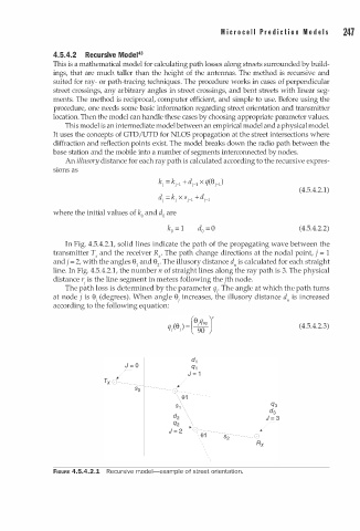
In Fig. 4.5.4.2.1, solid lines indicate the path of the propagating wave between the
transmitter T and the receiver R . The path change directions at the nodal point, j = 1
x
x
and j = 2, with the angles 8 1 and 8 • The illusory distance d" is calculated for each straight
2
line. In Fig. 4.5.4.2.1, the number n of straight lines along the ray path is 3. The physical
distance r is the line segment in meters following the jth node.
i
The path loss is determined by the parameter qi ' The angle at which the path turns
at node j is 8 (degrees). When angle 8 increases, the illusory distance d" is increased
i
i
according to the following equation:
(4.5.4.2.3)
FIGURE 4.5.4.2.1 Recursive model-example of street orientation.