
Page 286 - Integrated Wireless Propagation Models
P. 286
264 C h a p t e r F i v e
Also, in a close-in environment, there are four planes: one ground, one ceiling, and two
side planes. These four planes will generate four reflected waves received by the
receiver besides the direct wave. Because the transmitting antenna is usually set up
high and close to the ceiling, among the four reflected waves, only the ground-reflected
wave is a dominant wave because the reflected point on the ground from the ground
reflected wave is closer to the receiver than the other three reflected points on the other
three planes from the other three reflected waves. The three reflected points from three
reflected waves occurred further away from the receiver would scatter the energy after
reflected and cause the three reflected waves to carry the weak energy to the receiver.
Therefore, we may ignore the other three reflected waves and consider only the direct
wave and the ground-reflected wave as the two main components.
5.2. 1 . 1 Based on the Two-Ray Model
The close-in distance can be derived from the two-ray model, which was described in
20
1
Sec. . 9.1.3. The received signal power is expressed as
(1.9. . 3.1)
1
.
where the reflection coefficient a appeared in Eq. ( . 9 1 . 1 .2) as
1
v
2 1
£ sin8 - (E - cos 8 ) 12
,
,
1
1
1
" = £, sin 8 + (E - cos 8 ) 12
2 1
a (vertical) (1.9. . 1 .2)
1
1
,
and �<I> is the phase difference between the direct wave and reflected wave at the point
of reception, 8 is the incident angle, and £ , is listed in Eq. (1.9.1. 1 . 3) as
1
.
£, = £, - j60a'A (1.9 1 . 1 . 3)
where the permittivity £, is the principal component of the dielectric constant £,, a is the
conductivity of the dielectric medium in Siemens per meter, and 'A is the wavelength. 21
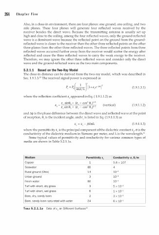
Some typical values of permittivity and conductivity for various common types of
media are shown in Table 5.2. . la.
l
Medium Permittivity e, Conductivity cr, 5/m
Copper 1 5.8 X 10⁷
Seawater 80 4
Rural ground (Ohio) 14 10-2
U r ban ground 3 10-4
Fresh water 80 10-3
Turf with short, dry grass 3 5 X 10⁻²
Turf with short, wet grass 6 1 X 10⁻¹
Bar , dry, sandy loam 2 3 X 10⁻²
e
e
Bar , sandy loam saturated with water 24 6 X 10⁻¹
TABLE 5.2.1.1a Data of e, on Different u r faces 22
S