
Page 287 - Integrated Wireless Propagation Models
P. 287
I n - B u i l d i n g ( P i c o c e l l ) P r e d i c t i o n M o d e l s 265
5.2. 1 . 1 . 1 . Estimate £ 23- 2 7
r
Since £, is the dominated factor in Eq. (1.9.1.1.3), we should look into the values of £,
from the building material.
Stone wall: Inside building £ , = 4.5
Outside building E = 7.9
,
Concrete wall: Inside building E = 5.4
,
Glass wall: Inside building £, = 2.3
5.2. 1.2 The Close-In Distance Is Determined When the
Reflection Coefficient a = 0
v
We may find the condition of the reflection coefficient a = 0 from Eq. (1.9.1 . 1 .2) as
v
2 1 ) 1 2
E s in91 = (E - COS 9 1 (5.2.1.2.1)
c
c
Solving Eq. (5.2.1.1), we get
. 1
sm e 1 = � (5.2.1.2.2)
E + 1
...; c
(5.2.1.2.3)
where the dielectric contant E consists of two parts-the permittivity £ , and the conduc
c
.
tivity cr, expressed in Eq. (1.9 1 . 1 . 3).
We select two from Table 5.2 1 . 1 b , the permittivities and the conductivities are listed
.
in the range 900 MHz to 2.44 GHz.
For wooden floor, £, = 3, and cr = 0.001, them E = - j 60 x 0.001 = 3 - j 0.06 A
A
3
c
A
7
For concrete ceiling/ floor, £, = 7, and cr = 0 .05 , then E = - j 60 x 0.05 = 7 - j 3.0 A
c
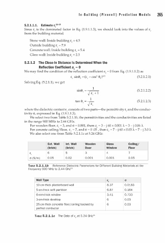
We also select one from Table 5.2.1.1c at 5.24 GHz:
Ext. Wall Int. Wall Wooden Glass Ceiling;
(brick) (brick) Door Window Floor
E 6 5 3 4 7
,
cr (S/m) 0.05 0.02 0.001 0.001 0.05
TABLE 5.2.1.1b Reference Dielectric Parameters for Different Building Materials at the
2
Frequency 900 H z to . 44 GHz 3
2
M
Wall Type E (J
r
10-cm-thick plasterboard wa l l 8.37 0.0183
5-cm-thick soft partition 6.87 0.164
6-mm-thick window 3.41 0.733
3-cm-thick desktop 6 0.03
25-cm-thick concrete floor/ce l i n g backed by 6 0.03
i
perfect conductor
4
TABLE 5.2.1.1c The Data of E at . 24 GHz 2
5
c