
Page 292 - Integrated Wireless Propagation Models
P. 292
270 C h a p t e r F i v e
1 5 0 meters
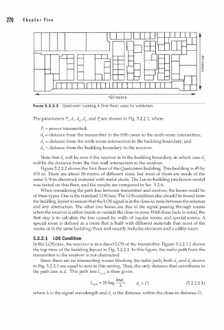
FIGURE 5.2.2.2 Qualcomm building A (first floor) used for validation.
The parameters P1, d1, d2, d3' and P, are shown in Fig. 5.2.2 1, where
P1 = power transmitted,
d1 = distance from the transmitter in the fifth room to the sixth-room intersection,
d 2 = distance from the sixth-room intersection to the building boundary, and
d3 = distance from the building boundary to the receiver.
Note that d3 will be zero if the receiver is in the building boundary, in which case d 2
will be the distance from the first wall intersection to the receiver.
Figure 5.2.2.2 shows the first floor of the Qualcomm building. This building is 45 by
150 m. There are about 50 rooms of different sizes, but most of them are made of the
5
same / 8-in sheetrock material with metal studs. The Lee in-building prediction model
was tested on this floor, and the results are compared in Sec. 5.2.6.
When considering the path loss between transmitter and receiver, the losses could be
of three types. One is the standard LOS loss. The LOS condition also should be found from
the building layout to ensure that the LOS signal is in the close-in zone between the antenna
and any obstruction. The other two losses are due to the signal passing through rooms
when the receiver is either inside or outside the close-in zone. With these facts in mind, the
first step is to calculate the loss caused by walls of regular rooms and special rooms. A
special room is defined as a room that is built with different materials than most of the
rooms of in the same building/floor and usually includes elevators and a utility room.
5.2.2. 1 LOS Condition
In the LOS case, the receiver is in a direct LOS of the transmitter. Figure 5.2.2.1.1 shows
.
the top view of the building layout in Fig. 5.2.2 1 . In this figure, the radio path from the
transmitter to the receiver is not obstructed.
Since there are no intersecting rooms blocking the radio path, both d2 and d3 shown
in Fig. 5.2.2.1 are equal to zero in this setting. Thus, the only distance that contributes to
the path loss is d1• This path loss L ws is then given:
L ws = 20 log � 1 (5.2.2.1.1)
4
where A is the signal wavelength and d1 is the distance within the close-in distance D .
e