
Page 295 - Integrated Wireless Propagation Models
P. 295
I n - B u i l d i n g ( P i c o c e l l ) P r e d i c t i o n M o d e l s 273
Transmitter Receiver
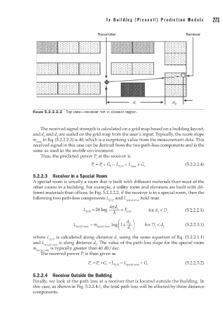
FIGURE 5.2.2.2.2 Top view-receiver not in close-in region.
The received signal strength is calculated on a grid map based on a building layout,
and d2 and d 1 are scaled on the grid map from the user's input. Typically, the room slope
m,oom in Eq. (5.2.2.2.3) is 40, which is a surprising value from the measurement data. This
received signal in this case can be derived from the two path-loss components and is the
same as used in the mobile environment.
Thus, the predicted power P, at the receiver is
P , = P, G, - L ws - L room G, (5.2.2.2.4)
+
+
5.2.2.3 Receiver in a Special Room
A special room is usually a room that is built with different materials than most of the
other rooms in a building. For example, a utility room and elevators are built with dif
ferent materials than offices. In Fig. 5.2.2.2.2, if the receiver is in a special room, then the
following two path-loss components L os and L . 1 room hold true:
L
specw
4ndl
L ws - 2 + F ws (5.2.2.2.1)
- 0 l og
-A-
( 2 d )
L al room = m special room log 1 + -- (5.2.2.3.1)
speci
d
l
where L ws is calculated along distance d using the same equation of Eq. (5.2.2. . 1 )
1
1
and L . 1 room is along distance d2• The value of the path-loss slope for the special room
specw
m . 1 room is typically greater than 40 db I dec.
specm
The received power P, is then given as
P , = P, G t - L LOS - [ special room G r (5.2.2.3.2)
+
+
5.2.2.4 Receiver Outside the Building
Finally, we look at the path loss at a receiver that is located outside the building. In
this case, as shown in Fig. 5.2.2.4.1, the total path loss will be affected by three distance
components.