
Page 293 - Integrated Wireless Propagation Models
P. 293
I n - B u i l d i n g ( P i c o c e l l ) P r e d i c t i o n M o d e l s 2TI
. . . � . � . . . ' . . . . . '
�
. ' 0 . . 0 . . o . . .. I . •
.. .
S
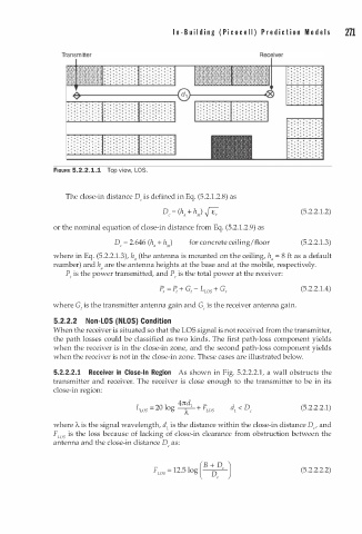
FIGURE 5.2.2.1.1 Top view, LO .
i
The close-in distance D i s defined n Eq. (5.2.1.2.8) as
c
)
D = c ( h + a h m '\/ c., (5.2.2.1.2)
1£ ,
or the nominal equation of close-in distance from Eq. (5.2 1 .2.9) as
.
D = 2.646 (h a + h,.,) for concrete ceiling/ floor (5.2.2.1.3)
c
where in Eq. (5.2.2.1.3), h a (the antenna is mounted on the ceiling, h a = 8 f t as a default
number) and h a are the antenna heights at the base and at the mobile, respectively.
P1 is the power transmitted, and P, is the total power at the receiver:
(5.2.2.1.4)
where G1 is the transmitter antenna gain and G, is the receiver antenna gain.
(
5.2.2.2 Non-LOS N L OS) Condition
When the receiver is situated so that the LOS signal is not received from the transmitter,
the path losses could be classified as two kinds. The first path-loss component yields
when the receiver is in the close-in zone, and the second path-loss component yields
when the receiver is not in the close-in zone. These cases are illustrated below.
5.2.2. . 1 Receiver in Close-In Region As shown in Fig. 5.2.2.2.1, a wall obstructs the
2
transmitter and receiver. The receiver is close enough to the transmitter to be in its
close-in region:
4nd
2
- 0 l og - A - + F ws (5.2.2.2.1)
i
L ws -
where A is the signal wavelength, d1 is the distance within the close-in distance D c , and
Fws is the loss because of lacking of close-in clearance from obstruction between the
antenna and the close-in distance D as:
c
(5.2.2.2.2)