
Page 289 - Integrated Wireless Propagation Models
P. 289
I n - B u i l d i n g ( P i c o c e l l ) P r e d i c t i o n M o d e l s 267
_ fL!"..:::..
L_ _ _ _ _ _ _ _ _ _ _ _ _
1-4'- - - - - - - - - -d .. 1
i
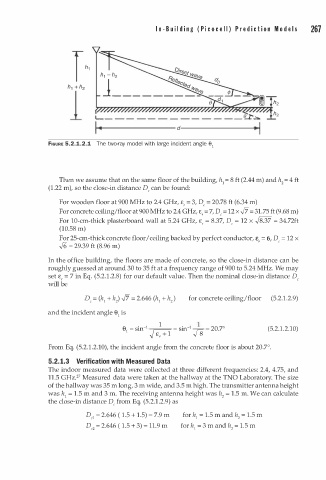
FIGURE 5.2.1.2.1 The two-ray model with large n cident angle 61
4
Then we assume that on the same floor of the building, h = 8 f t (2.44 m) and h = f t
1
2
(1.22 m), so the close-in distance D can be found:
c
For wooden floor at 900 MHz to 2.4 GHz, £, = 3, D c = 20.78 ft (6.34 m)
For concrete ceiling/floor at 900 MHz to 2.4 GHz, £ , = 7, D = 12 x ft 3 1.75 ft (9.68 m)
=
e
For 10-cm-thick plasterboard wall at 5.24 GHz, £ = 8.37, D = 12 x .J8.37 = 34.72ft
c
r
(10.58 m)
For 25-cm-thick concrete floor I ceiling backed by perfect conductor, £ = 6, D = 12 x
c
,
.J6 = 29.39 ft (8.96 m)
In the office building, the floors are made of concrete, so the close-in distance can be
roughly guessed at around 30 to 35 ft at a frequency range of 900 to 5.24 MHz. We may
set £, = 7 in Eq. (5.2.1.2.8) for our default value. Then the nominal close-in distance D e
will be
for concrete ceiling/floor (5.2.1.2.9)
and the incident angle 8 is
1
1
1
8 = sin· 1 1 = sin- -- = 20.7° (5.2.1.2.10)
1
f£:+ J8
From Eq. (5.2.1.2.10), the incident angle from the concrete floor is about 20.7°.
5.2. 1.3 Verification with Measured Data
The indoor measured data were collected at three different frequencies: 2.4, 4.75, and
2
11.5 GHz. 7 Measured data were taken at the hallway at the TNO Laboratory. The size
3
of the hallway was 35 m long, m wide, and 3.5 m high. The transmitter antenna height
was h 1 = 1 . 5 m and 3 m. The receiving antenna height was h 2 = 1.5 m. We can calculate
the close-in distance D from Eq. (5.2.1.2.9) as
c
1
1
D = 2.646 ( 1 . 5 + 1 . 5) = 7.9 m for h = . 5 m and h = . 5 m
1
el
2
1
c2 2
D = 2.646 ( 1 . 5 + 3) = 11.9 m for h = 3 m and h = 1.5 m