
Page 294 - Integrated Wireless Propagation Models
P. 294
272 C h a p t e r F i v e
Receiver
Transmitter
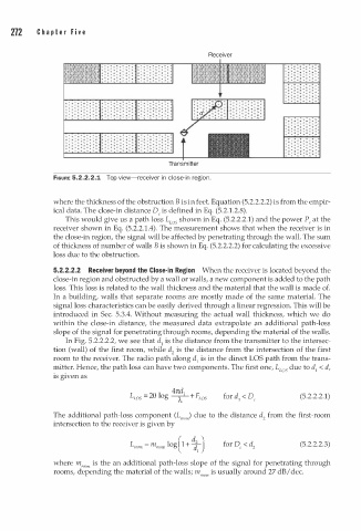
FIGURE 5.2.2.2.1 Top view-receiver in close-in region.
where the thickness of the obstruction B is in feet. Equation (5.2.2.2.2) is from the empir
ical data. The close-in distance De is defined in Eq. (5.2.1.2.8).
This would give us a path loss L s shown in Eq. (5.2.2.2.1) and the power P, at the
LO
receiver shown in Eq. (5.2.2.1 . 4). The measurement shows that when the receiver is in
the close-in region, the signal will be affected by penetrating through the wall. The sum
of thickness of number of walls B is shown in Eq. (5.2.2.2.2) for calculating the excessive
loss due to the obstruction.
5.2.2.2.2 Receiver beyond the Close-in Region When the receiver is located beyond the
close-in region and obstructed by a wall or walls, a new component is added to the path
loss. This loss is related to the wall thickness and the material that the wall is made of.
In a building, walls that separate rooms are mostly made of the same material. The
signal loss characteristics can be easily derived through a linear regression. This will be
introduced in Sec. 5.3.4. Without measuring the actual wall thickness, which we do
within the close-in distance, the measured data extrapolate an additional path-loss
slope of the signal for penetrating through rooms, depending the material of the walls.
In Fig. 5.2.2.2.2, we see that d1 is the distance from the transmitter to the intersec
tion (wall) of the first room, while d2 is the distance from the intersection of the first
room to the receiver. The radio path along d1 is in the direct LOS path from the trans
mitter. Hence, the path loss can have two components. The first one, L s due to d1 < d,
LO
is given as
LOS -
4
l
L - 20 og - A- F (5.2.2.2.1)
7td + LOS
1
The additional path-loss component (L,00,) due to the distance d2 from the first-room
intersection to the receiver is given by
( � )
L room = m,00, log 1 + 1 (5.2.2.2.3)
where m room is the an additional path-loss slope of the signal for penetrating through
rooms, depending the material of the walls; m room is usually around 27 dB I dec.