
Page 296 - Integrated Wireless Propagation Models
P. 296
274 C h a p t e r F i v e
Transmitter Receiver
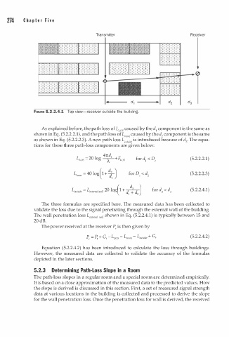
FIGURE 5.2.2.4.1 Top view-receiver outside the building.
As explained before, the path loss of L ws caused by the d component is the same as
1
shown in Eq. (5.2.2.2.1), and the path loss of L,00, caused by the d component is the same
2
as shown in Eq. (5.2.2.2.3). A new path loss L outsi de is introduced because of d3• The equa
tions for these three path-loss components are given below:
47td l
L ws - - 20 og -- + F ws for d < D, (5.2.2.2.1)
1
1
A
(5.2.2.2.3)
L outsi de = L xtemal wall 20 log ( 1 + � ) (5.2.2.4.1)
e
d
1 d
2
The three formulas are specified here. The measured data has been collected to
validate the loss due to the signal penetrating through the external wall of the building.
The wall penetration loss L xtema t wau shown in Eq. (5.2.2.4.1) is typically between 15 and
e
20 dB.
The power received at the receiver P, is then given by
P, = P. + G t - L LOS - L room - L outsi de + G, (5.2.2.4.2)
Equation (5.2.2.4.2) has been introduced to calculate the loss through buildings.
However, the measured data are collected to validate the accuracy of the formulas
depicted in the later sections.
5.2.3 Determining Path-Loss Slope in a Room
The path-loss slopes in a regular room and a special room are determined empirically.
It is based on a close approximation of the measured data to the predicted values. How
the slope is derived is discussed in this section. First, a set of measured signal strength
data at various locations in the building is collected and processed to derive the slope
for the wall penetration loss. Once the penetration loss for wall is derived, the received