
Page 288 - Integrated Wireless Propagation Models
P. 288
266 C h a p t e r F i v e
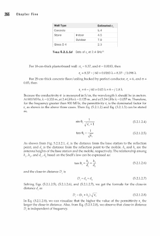
Wall Type Estimated e,
Concrete 5.4
Stone I n door 4.5
Outdoor 7 . 9
Glass D 4 2.3
2
TABLE 5.2.1.1d Data of e, at 2.4 GHz 5
For 10-cm-thick plasterboard wall : £ , = 8.37, and a = 0.0183, then
£, = 8.37 -j 60 X 0.0183 A = 8.37- j 1 . 098 A
For 25-cm-thick concrete floor I ceiling backed by perfect conductor, £, = 6, and a =
0.03, then
£, = 6 -j 60 X 0.03 A = 6 - j 1.8 A
Because the conductivity a is measured in S/m, the wavelength A should be in meters.
A
A
At 900 MHz, = 0.333 m, at 2.4 GHz = 0.125 , and at 5.24 GHz = 0.057 m. Therefore,
A
m
for the frequency greater than 900 MHz, the permittivity £, is the dominated factor for
£, as shown in the above three cases. Then Eq. (5.2.1.2) and Eq. (5.2 . 1 .3) can be stated
as,
1
. 8 1
sm � (5.2.1.2.4)
v £, + 1
1
tan 81 = r;: (5.2.1.2.5)
E
v ,
As shown from Fig. 5.2.1.2.1, d1 is the distance from the base station to the reflection
point, and d2 is the distance from the reflection point to the mobile. h1 and h2 are the
antenna heights of the base station and the mobile, respectively. The relationship among
h1 , h2 , and d1 , d2 based on the Snell's law can be expressed as:
h h
tan 81 = f 1 = i 2 (5.2.1.2.6)
and the close-in distance D is
c
(5.2.1.2.7)
Solving Eqs. (5.2.1.2.5), (5.2 1 . 2.6), and (5.2.1.2.7), we get the formula for the close-in
.
distance d as
c
(5.2.1.2.8)
In Eq. (5.2.1.2.8), we can visualize that the higher the value of the permittivity £, the
larger the close-in distance. Also, from Eq. (5.2.1.2.8), we observe that close-in distance
D, is independent of frequency.