
Page 318 - Integrated Wireless Propagation Models
P. 318
296 C h a p t e r F i v e
e � "'
e�
�
co "
d 8.4 meters
3 r d floor access point Tx
J] �
E
C') t r-------------'--��-------1
2nd floor access point Tx
]]
1------------L--�------1
1st floor 1st floor access
test spot Rx point Tx
E
• Access point Tx
Test spot Rx
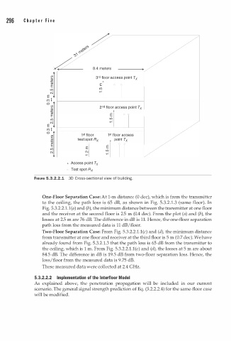
FtGURE 5.3.2.2.1 3D Cross-sectional view of building.
One-Floor Separation Case: At 1-m distance (0 dec), which is from the transmitter
to the ceiling, the path loss is 65 dB, as shown in Fig. 5.3. . 1 . 3 (same floor). In
2
l
Fig. 5.3.2.2. . l ( a) and (b), the minimum distance between the transmitter at one floor
and the receiver at the second floor is 2.5 m (0.4 dec). From the plot (a) and (b), the
losses at 2.5 m are 76 dB. The difference in dB is 11. Hence, the one-floor separation
path loss from the measured data is 11 dB/floor.
Two-Floor Separation Case: From Fig. 5.3.2. . l . l ( c) and (d), the minimum distance
2
from transmitter at one floor and receiver at the third floor is 5 m (0.7 dec). We have
already found from Fig. 5.3.2.1.3 that the path loss is 65 dB from the transmitter to
m
l
the ceiling, which is m . From Fig. 5.3.2.2. . l ( c) and (d), the losses at 5 a re about
1
84.5 dB. The difference in dB is 19.5 dB from two-floor separation loss. Hence, the
loss/floor from the measured data is 9.75 dB.
These measured data were collected at 2.4 GHz.
5.3.2.2.2 Implementation of the lnterfloor Model
As explained above, the penetration propagation will be included in our current
scenario. The general signal strength prediction of Eq. (5.2.2.2.4) for the same-floor case
will be modified.