
Page 320 - Integrated Wireless Propagation Models
P. 320
298 C h a p t e r F i v e
North 4th to 2nd Floor
78
*
80
*
82
84
co * � -
""0 86
c *
(/) 88 1- * + *1* . . . . . . . . . . . . . . . . . . . . . . ;
(/)
.2
.r: 90 . i* · · ·
Cil
a_
92
94
96
98
0.7 0.8 0.9 1.2 1.3 1.4 1.5 1.6 1.7 X
Distance between Tx and Rx in meter (dec scale) ( 1 0 x in meters)
(c)
South 2nd to 4th Floor
80 *
*
co
""0 * -�
-� *'
(/) *
(/) 85 . .
.2 ";¥- *
.r: '* *
Cil l * Lv
a_ .
* 7f"
90 *
*
*
95 L_ --� __ __ _L __ __ L_ __ __ __ __ __ __ __ __ __ __
1.2
1.6
�
1.4
1.5
0.7 0.8 0.9 � _L 1.3 __ L_ � _L � 1.7 X
1 . 1
Distance between Tx and Rx in meter (dec scale) ( 1 0 x in meters)
(d)
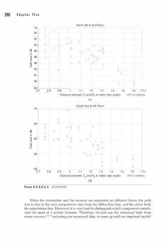
FIGURE 5.3.2.2.1.1 (Continued )
When the transmitter and the receiver are separated on different floors, the path
loss is due to the two components: one from the diffraction loss, and the other from
the penetration loss. However, it is very hard to distinguish which component contrib
utes the most at a certain location. Therefore, we just use the measured data from
many sources/·32 -36 including our measured data, to come up with an empirical model.